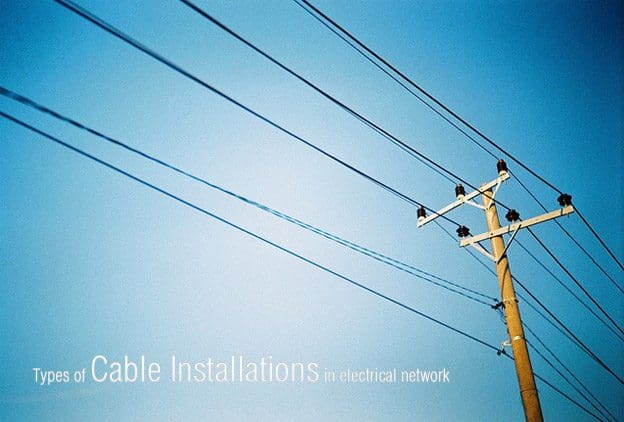
Types of cable installations in electrical network
Introduction to installing power cables
There are a variety of ways to install power distribution cables. Each method ensures distribution of power with a unique degree of reliability, safety, economy, and quality for any specific set of conditions.
These conditions include the electrical characteristics of the power system, the distance and terrain of distribution, and the expected mechanical and environmental conditions.
1. Open-Wire
Open-wire construction consists of uninsulated conductors on insulators which are mounted on poles or structures. The conductor may be bare or it may have a thin covering for protection from corrosion or abrasion. The attractive features of this method are its low initial cost and the fact that damage can be detected and repaired quickly.
On the other hand, the uninsulated conductors are a safety hazard and are also highly susceptible to mechanical damage and electrical outages resulting from short circuits caused by birds or animals. Proper vertical clearances over roadways, walkways, and structures are critical. Exposed open-wire circuits are also more susceptible to the effects of lightning than other circuits, however, these effects may be minimized by the use of overhead ground wires and lightning arresters.
In addition, there is an increased hazard where crane or boom truck use may be involved. In some areas contamination on insulators and conductor corrosion can result in high maintenance costs.
2. Aerial Cable
Aerial cable consists of fully insulated conductors suspended above the ground. This type of installation is used increasingly, generally for replacing open wiring, where it provides greater safety and reliability and requires less space.
Properly protected cables are not a safety hazard and are not easily damaged by casual contact.
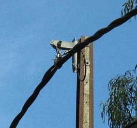 |
| 415 volt insulated aerial bundled cables (ABC) |
They do, however, have the same disadvantage as open-wire construction, requiring proper vertical clearances over roadways, walkways, and structures.
2.1 Supports
Aerial cables may be either self-supporting or messenger-supported. They may be attached to pole lines or structures. Self-supporting aerial cables have high tensile strength for this application. Cables may be messenger-supported either by spirally wrapping a steel band around the cables and the messenger or by pulling the cable through rings suspended from the messenger.
2.2 Distance
Self-supporting cable is suitable for only relatively short distances, with spans in the range of 100-150 feet. Messenger-supported cable can span relatively large distances, of over 1000 feet, depending on the weight of the cable and the tensile strength of the messenger. For this reason, aerial cable that must span relatively large distances usually consists of aluminum conductors to reduce the weight of the cable assembly.
The supporting messenger provides high strength to withstand climatic rigors or mechanical shock. It may also serve as the grounding conductor of the power circuit.
3. Above-Ground Conduits
Rigid steel conduit systems afford the highest degree of mechanical protection available in above-ground conduit systems. Unfortunately, this is also a relatively high-cost system. For this reason their use is being superseded, where possible, by other types of conduit and wiring systems.
Where applicable, rigid aluminum, intermediate-grade steel conduit, thin-wall EMT, intermediate-grade metal conduit, plastic, fiber and asbestos-cement ducts are being used.
4. Underground Ducts
Underground ducts are used where it is necessary to provide a high degree of safety and mechanical protection, or where above-ground conductors would be unattractive.
 |
| Underground cable duct on street |
4.1 Construction
Underground ducts use rigid steel, plastic, fiber, and asbestos-cement conduits encased in concrete, or precast multi-hole concrete with close fitting joints.
Clay tile is also used to some extent. Where the added mechanical protection of concrete is not required, heavy wall versions of fiber and asbestos-cement and rigid steel and plastic conduits are direct buried.
4.2. Cables
Cables used in underground conduits must be suitable for use in wet areas, and protected against abrasion during installation.
5. Direct Burial
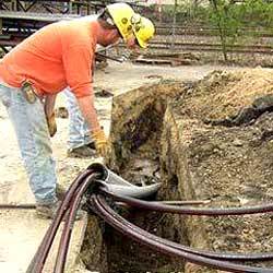
Underground direct buried power cables
Cables may be buried directly in the ground where permitted by codes and only in areas that are rarely disturbed. The cables used must be suitable for this purpose, that is, resistant to moisture, crushing,soil contaminants, and insect and rodent damage. While direct-buried cable cannot be readily added to or maintained, the current carrying capacity is usually greater than that of cables in ducts. Buried cable must have selected backfill.
It must be used only where the chance of disturbance is unlikely. The cable must be suitably protected, however, if used where the chance of disturbance is more likely to occur.
Relatively recent advances in the design and operating characteristics of cable fault location equipment and subsequent repair methods and material have diminished the maintenance problem.
6. Underwater (Submarine) Cable
Submarine cable is used only when no other cable system can be used. It supplies circuits that must cross expanses of water or swampy terrain.
6.1 Construction
Submarine cable generally consists of a lead sheathed cable and is usually armored.Insulation material should be XLP or EPR, except when paper insulation is justified because of its high resistance to, and freedom from, internal discharge or corona.
Multiconductor construction should be used, unless limited by physical factors. The lead sheathing usually consists of a copper-bearing lead material, however, other alloys may be required when special conditions warrant nonstandard sheathing. The most common type of armoring material used for submarine cables is the spirally wrapped round galvanized steel wire.
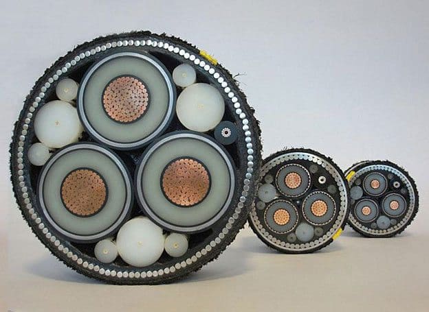
Standard applications for submarine power cables to connect mainland areas or cities via water passages. This applies to mainland-to-island connections. Many of these networks and connections are getting older and need to be overhauled. We are constantly working on the continuous refinement of these products to reduce environmental effects (precisely during the laying process) and losses during power transmission (using new materials).
In this type of cable, asphalt impregnated jute is usually applied over the lead sheath and the wire armor is applied over the jute to reduce mechanical damage and electrolytic corrosion. An additional covering of the asphalt impregnated jute may be applied over the wire armor.
Nonmetallic sheathed cables are sometimes suitable for certain submarine applications. The cable must be manufactured specifically for submarine service and, generally, has an increased insulation thickness. The cable may require wire armor and should have electrical shielding for all voltage ratings above 600 V.
6.1 Installation
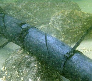
Installed underwater sea submarine cable
Submarine cable should lie on the floor of the body of water and should have ample slack so that slight shifting caused by current or turbulence will not place excessive strain on the cable. Where the cable crossing is subject to flow or tidal currents, anchors are often used to prevent excessive drifting or shifting of the cable. In addition to laying cables directly on the bottom, burying cable in a trench using the jetwater method should be considered.
Cables must be buried in waters where marine traffic is present. The depth of burial should be enough to prevent damage caused by dragging anchors, which may be in excess of 15 feet for large ships on sandy bottoms.
Warning signs located on shore at the ends of the submarine cable should be provided to prohibit anchoring in the immediate vicinity of the cable.
Grounding of Cable Systems
For safety and reliable operation, the shields and metallic sheaths of power cables must be grounded. Without such grounding, shields would operate at a potential considerably above ground. Thus, they would be hazardous to touch, and would incur rapid degradation of the jacket or other material intervening between shield and ground.
This is caused by the capacitive charging current of the cable insulation which is approximately 1 milliampere (mA) per foot of conductor length. This current normally flows at a power frequency between the conductor and the earth electrode of the cable, normally the shield. In addition, the shield or metallic sheath provides the fault return path in the event of insulation failure, permitting rapid operation of the protection devices.
Grounding Conductor
The grounding conductor, and its attachment to the shield or metallic sheath, normally at a termination or splice, should have an ampacity no lower than that of the shield.
In the case of a lead sheath, the grounding conductor must be able to carry the available fault current over its duration without overheating. Attachment to shield or sheath is frequently by means of solder, which has a low melting point; thus an adequate area of attachment is required.
Grounding Methods
The cable shield lengths may be grounded at both ends or at only one end.
If grounded at only one end, any possible fault current must traverse the length from the fault to the grounded end, imposing high current on the usually very thin shield conductor. Such a current could damage or destroy the shield, and require replacement of the entire cable rather than only the faulted section. With both ends grounded, the fault current would divide and flow to both ends, reducing the duty on the shield, with consequently less chance of damage.
There are modifications of both systems. In one, single-ended grounding may be attained by insulating the shields at each splice or sectionalizing point, and grounding only the source end of each section. This limits possible shield damage to only the faulted section.
Multiple grounding, rather than just double-ended grounding, is simply the grounding of the cable shield or sheath at all access points, such as manholes or pull boxes. This also limits possible shield damage to only the faulted section.
Resource: Electric Power Distribution Systems Operations by NAVFAC MO-201, April 1990
Using CarRental8 you can find the most affordable rental cars from over 50,000 international locations.
ReplyDeletenice article. Amwire provide automotive cable suppliers
ReplyDeleteThis blog provides excellent insights into HDPE duct spacers, crucial for cable installations. These spacers ensure proper alignment and separation of cables, enhancing durability and efficiency. HDPE duct spacers are resistant to harsh weather and chemicals, making them ideal for long-term use. Duct spacer exporters in Gujarat offer high-quality options.
ReplyDeleteGreat breakdown of the different cable installation methods! It’s interesting how the choice of setup can affect both safety and performance. Selecting the right type of electrical power cables for specific conditions really makes a huge difference in ensuring long-term reliability.
ReplyDelete