 |
| Substations and Distribution Substations Overview |
Introduction
High voltage substations are interconnection points within the power transmission and distribution systems between regions and countries.
Different applications of substations lead to high voltage substations with and without power transformers:
- Step up from a generator voltage level to a high voltage system (MV/HV)- Power plants (in load centers)- Renewable power plants (e.g., windfarms)
- Transform voltage levels within the high voltage system (HV/HV)
- Step down to medium voltage level of a distribution system (HV/MV)
- Interconnection in the same voltage level
Scope
High
voltage substations comprise not only the high voltage equipment which
is relevant for the functionality in the power supply system.
High voltage substations
are planned and constructed comprising high voltage switchgear, medium
voltage switchgear, major components such as high voltage equipment and
transformers, as well as all ancillary equipment such as auxiliaries,
control systems, protective equipment and so on, on a turnkey basis or
even as general contractor.
The installations supplied worldwide
range from basic substations with a single busbar to interconnection
substations with multiple busbars, or a breaker–and–half arrangement for
rated voltages up to 800 kV, rated currents up to 8,000A.
A and short circuit currents up to 100 kA.
Circuit configuration
 High Voltage Substation High Voltage Substation |
High voltage substations
are points in the power system where power can be pooled from
generating sources, distributed and transformed, and delivered to the
load points.
Substations are interconnected with each other, so that the power system becomes a meshed network.
This increases the reliability of the power supply system by providing
alternate paths for flow of power to take care of any contingency, so
that power delivery to the loads is maintained and the generators do not
face any outage.
The high voltage substation is critical component in the power system,
and the reliability of the power system depends upon the substation.
Therefore, the circuit configuration of the high voltage substation has
to be selected carefully.
Busbars are the part of the substation
where all the power is concentrated from the incoming feeders, and
distributed to the outgoing feeders. That means that the reliability of
any high voltage substation depends on the reliability of the busbars
present in the power system.
An outage of any busbar can have dramatic effects on the power system.
An outage of a busbar leads to the outage of the transmission lines connected to it.
As
a result, the power flow shifts to the surviving healthy lines that are
now carrying more power than they are capable of. This leads to
tripping of these lines, and the cascading effect goes on until there is
a blackout or similar situation.
The importance of busbar reliability should be kept in mind when taking a look at the different busbar systems that are prevalent.
Protective measures
The protective measures can be categorized as personal protection and functional protection of the substations.
Personal protection
- Protective measures against direct contact, i.e., through appropriate covering, obstruction, through sufficient clearance appropriate positioned protective devices, and minimum height
- Protective measures against indirect touching by means of relevant earthing measures in accordance with IEC 61936/DIN VDE 0101 or other required standards
- Protective measures during work on equipment, i.e., installation must be planned so that the specifications of DIN EN 50110 (VDE 0105) (e.g., five safety rules) are observed.
Functional protection
- Protective measures during operation, e.g., use of switchgear interlocking equipment
- Protective measures against voltage surges and lightning strikes
- Protective measures against fire, water and, if applicable, noise
Stresses
- Electrical stresses, e.g., rated current, short circuit current, adequate creepage distances and clearances
- Mechanical stresses (normal stressing), e.g., weight, static and dynamic loads, ice, wind
- Mechanical stresses (exceptional stresses), e.g., weight and constant loads in simultaneous combination with maximum switching forces or short circuit forces, etc.
- Special stresses, e.g., caused by installation altitudes of more than 1,000 m above sea level, or by earthquakes
Arrangement and modules
 |
| High Voltage Substation Elements |
Arrangement
The system is off the enclosed 1-phase or 3-phase type.
The
assembly consists of completely separate pressurized sections, and is
thus designed to minimize any danger to the operating staff and risk of
damage to adjacent sections, even if there should be trouble with the
equipment.
Rupture diaphragms are provided to prevent the
enclosures from bursting discs in an uncontrolled manner. Suitable
deflectors provide protection for the operating personnel.
For maximum operating reliability, internal relief devises are not installed, because these would affect adjacent compartments.
The
modular design, complete segregation, arc-proof bushing and plug-in
connections allow speedy removal and replacement of any section with
only minimal effects on the remaining pressurized switchgear.
Busbars
All busbars of the enclosed 3-phase or the 1-phase type are connected with plug from the one bay to the next.
Circuit breakers
 |
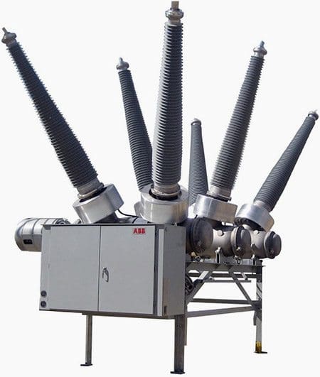
ABB - High voltage dead-tank circuit breaker 362 kV, max. 63 kA 362PMI
|
The circuit breakers operate according to the dynamic self-compression principle.
The number of interrupting units per phase depends on the circuit
breaker’s performance. The arcing chambers and the circuit breaker
contacts are freely accessibly.
The circuit breaker is suitable
for out-of-phase switching and designed to minimize overvoltages. The
specified arc interruption performance has to be consistent across the
entire operating range, from line-charging currents to full short
circuit currents.
The circuit breaker is designed to withstand at least 10 operations (depending on the voltage levels) at full short circuit rating.
Opening
the circuit breaker for service or maintenance is not necessary. The
maximum tolerance for phase displacement is 3ms, that is, the time
between the first and the last pole’s opening or closing.
A standard station battery that is required for control and tripping may also be used for recharging the operating mechanism.
The
drive and the energy storage system are provided by a stored energy
spring mechanism that holds sufficient energy for all standard IEC
close-open duty cycles.
The control system provides alarms signals
and internal interlocks but inhibits tripping or closing of the circuit
breaker when the energy capacity in the energy storage system
is insufficient or the SF6 density within the circuit breaker drops
below the minimum permissible level.
Disconnectors
 |
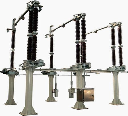
| Transmission line disconnect switch |
All disconectors (isolators) are of the single-break type.
DC motor operation (110, 125, 220 or 250 V)
which is fully suited to remote operation, and a manual emergency
operating mechanism are provided. Each motor operating mechanism is
self-contained and equipped with auxiliary switches in addition to the
mechanical indicators.
The bearings are lubricated for life.
Earthing switches
 |
| High voltage outdoor earthing switch (126kV, 252kV) |
Work-in
progress earthing switches are generally provided on either side of the
circuit breaker. Additional earthing switches may be used to earth
busbar sections or other groups of the assembly.
DC motor operation (110, 125, 220 or 250 V)
that is fully suited for remote operation and a manual emergency
operating mechanism are provided. Each motor operating mechanism is
self-contained and equipped with auxiliary position switches in addition
to the mechanical indicators. The bearings are lubricated for life.
Make proof high-speed earthing switches are generally installed at the
cable and overhead line terminals.
They are equipped with a rapid closing mechanism to provide short circuit making capacity.
Instrument transformers
 |
| SF6 gas insulated high-voltage current transformer (72.5 - 800 KV) - Trench Group |
Current transformers (CTs)
are of the dry type design. Epoxy resin is not used for
insulation purposes. Voltage transformers are of the inductive type,
with ratings up to 200 VA.
Cable terminations
1-phase
or 3-phase, SF6 gas insulated, metal enclosed cable end housing are
provided. The cable manufacturer has to supply the stress cone and
suitable sealings to prevent oil or gas from leaking into the SF6
switchgear.
The cable end housing is suitable for oil type, gas-pressure type cables with plastic insulation (PE, PVC, etc.).
Additionally,
devices for safety isolating a feeder cable and connecting a high
voltage test cable to the switchgear or cable will be provided.
Overhead line terminations
The terminations for connecting overhead lines come complete with SF6-to-air bushings but without line clamps.
Control and monitoring
As a standard, an electromechanical or solid-state interlocking control board is supplied for each switchgear bay. This fault-tolerant interlocking system prevents all operating malfunctions.
Mimic
diagrams and position indicators provide the operating personnel with
clear operating instructions. Provisions for remote control are
included. Gas compartments are constantly monitored by density monitors
that provide alarm and blocking signals via contacts.
To be continued…
Thanks for visiting this site. I will continue to add new topics.
ReplyDelete