Sunday 31 March 2013

Solar Power Tower

Solar tower - Power plant
Solar tower - Power plant. In solar power stations, mirrors are used to concentrate sunlight and convert it into thermal energy). This process enables temperatures of more than 1000 degrees Celsius to be achieved, which can be used to generate electricity, among other things.

Solar power towers generate electric power from sunlight by focusing concentrated solar radiation on a tower mounted heat exchanger (receiver). The system uses hundreds to thousands of sun-tracking mirrors called heliostats to reflect the incident sunlight onto the receiver. These plants are best suited for utility-scale applications in the 30 to 400 MWe range. In a molten-salt solar power tower, liquid salt at 290ºC (554ºF) is pumped from a ‘cold’ storage tank through the receiver where it is heated to 565ºC (1,049ºF) and then on to a ‘hot’ tank for storage.
When power is needed from the plant, hot salt is pumped to a steam generating system that produces superheated steam for a conventional Rankinecycle turbine/generator system. From the steam generator, the salt is returned to the cold tank where it is stored and eventually reheated in the receiver.
Figure 1 is a schematic diagram of the primary flow paths in a molten-salt solar power plant.
Determining the optimum storage size to meet power-dispatch requirements is an important part of the system design process. Storage tanks can be designed with sufficient capacity to power a turbine at full output for up to 13 hours.

Solar tower configuration
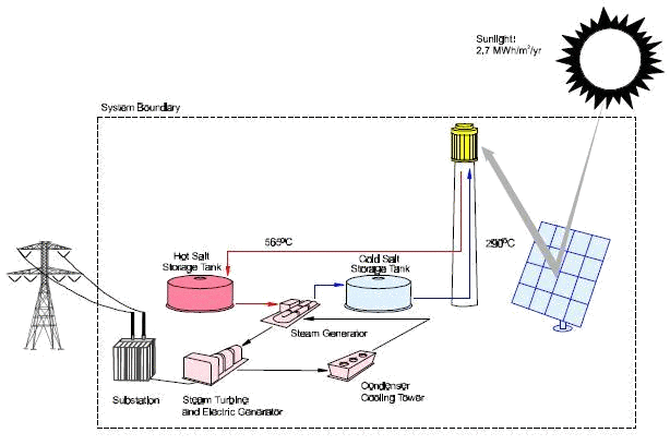
Figure 1. Molten-salt power tower system schematic (Solar Two, baseline configuration).


The heliostat field that surrounds the tower is laid out to optimize the annual performance of the plant. The field and the receiver are also sized depending on the needs of the utility. In a typical installation, solar energy collection occurs at a rate that exceeds the maximum required to provide steam to the turbine.
Consequently, the thermal storage system can be charged at the same time that the plant is producing power at full capacity. The ratio of the thermal power provided by the collector system (the heliostat field and receiver) to the peak thermal power required by the turbine generator is called the solar multiple.
With a solar multiple of approximately 2.7, a molten-salt power tower located in the California Mojave desert can be designed for an annual capacity factor of about 65%. (Based on simulations at Sandia National Laboratories with the SOLERGY [1] computer code.) Consequently, a power tower could potentially operate for 65% of the year without the need for a back-up fuel source. Without energy storage, solar technologies are limited to annual capacity factors near 25%.
The dispatchability of electricity from a molten-salt power tower is illustrated in Figure 2, which shows the loaddispatching capability for a typical day in Southern California. The figure shows solar intensity, energy stored in the hot tank, and electric power output as functions of time of day. In this example, the solar plant begins collecting thermal energy soon after sunrise and stores it in the hot tank, accumulating energy in the tank throughout the day. In response to a peak-load demand on the grid, the turbine is brought on line at 1:00 PM and continues to generate power until 11 PM.
Figure 2. Dispatchability of molten-salt power towers
Because of the storage, power output from the turbine generator remains constant through fluctuations in solar intensity and until all of the energy stored in the hot tank is depleted. Energy storage and dispatchability are very important for the success of solar power tower technology, and molten salt is believed to be the key to cost effective energy storage.
Power towers must be large to be economical. Power tower plants are not modular and can not be built in the smaller sizes of dish/Stirling or trough-electric plants and be economically competitive, but they do use a conventional power block and can easily dispatch power when storage is available.
In the United States, the Southwest is ideal for power towers because of its abundant high levels of insolation and relatively low land costs. Similar locations in northern Africa, Mexico, South America, the Middle East, and India are also well-suited for power towers.

System Benefits -Energy Storage

The availability of an inexpensive and efficient energy storage system may give power towers a competitive advantage.
Table 2 provides a comparison of the predicted cost, performance, and lifetime of solar-energy storage technologies for hypothetical 200 MW plants [5,6].

Installed cost of energy storage for a 200 MW plant
($/kWhre)
Lifetime of storage system
(years)
Round-trip storage efficiency
(%)
Maximum operating temperature
(C/ºF)
Molten-Salt Power Tower303099567/1,053
Synthetic-Oil Parabolic Trough2003095390/734
Battery Storage Grid Connected500 to 8005 to 1076N/A
Thermal-energy storage in the power tower allows electricity to be dispatched to the grid when demand for power is the highest, thus increasing the monetary value of the electricity. Much like hydro plants, power towers with salt storage are considered to be a dispatchable rather than an intermittent renewable energy power plant.
For example, Southern California Edison company gives a power plant a capacity payment if it is able to meet their dispatchability requirement: an 80% capacity factor from noon to 6 PM, Monday through Friday, from June through September.
Detailed studies have indicated that a solar-only plant with 4 hours of thermal storage can meet this dispatchability requirement and thus qualify for a full capacity payment.
While the future deregulated market place may recognize this value differently, energy delivered during peak periods will certainly be more valuable.
Besides making the power dispatchable, thermal storage also gives the power-plant designer freedom to develop power plants with a wide range of capacity factors to meet the needs of the utility grid. By varying the size of the solar field, solar receiver, and size of the thermal storage, plants can be designed with annual capacity factors ranging between 20 and 65% (see Figure 6).
Economic studies have shown that levelized energy costs are reduced by adding more storage up to a limit of about 13 hours (~65% capacity factor). While it is true that storage increases the cost of the plant, it is also true that plants with higher capacity factors have better economic utilization of the turbine, and other balance of plant equipment.
Since salt storage is inexpensive, reductions in LEC due to increased utilization of the turbine more than compensates for the increased cost due to the addition of storage.
Figure 6. In a solar power tower, plant design can be altered to achieve different capacity factors.
Figure 6. In a solar power tower, plant design can be altered to achieve different capacity factors
.
To increase capacity factor for a given turbine size, the designer would (1) increase the number of heliostats, (2) enlarge the thermal storage tanks, (3) raise the tower, and (4) increase the receiver dimensions.

Solar Energy And Silver

The solar industry isn’t the largest consumer of silver, but it is a growing market that could give silver producers a boost. Most of the markets that silver serves follow traditional supply-demand economics and therefore competition is based on price, product line, and service, for example. However, in the presence of a hyper-growth industry such as the photovoltaic industry (and especially the thin-film photovoltaic industry), companies that recognize new or growing opportunities relating to photovoltaics, and that tailor their offerings and services to capitalize on those opportunities, will stand to benefit ahead of the others.
A particularly good example of this phenomenon is the use of indium. While indium’s predominant use is for ITO – the main transparent conductor used by the display industry it is also a critical (and costly) component of the thin-film PV technology referred to as CIGS (copper indium/gallium diselenide).
Indium is an extreme example, since it is such a large component of CIGS PV material costs and since CIGS PV is expected to make up close to 10 percent of the indium market by 2016; however, a similar situation applies to a number of other metals, including silver. These metals are well-established industrially, but are also used (or potentially used) in a photovoltaic niche that presents a significant growth market.
While the overall markets for silver are dominated mainly by its established, “conventional” uses, there are a number of emerging technologies that also use silver, and these rapidly growing technologies will account for a disproportionate amount of the growth in the silver market.

Silver in Electronics: Market Evolution

Silver, including easily applied silver inks and pastes, is widely used in the electronics industry. It is easy to see why: Silver is the most conductive metal, bar none, and its oxide is also conductive, minimizing the impact of the oxidation that is unavoidable with almost any metal.
It has been used as a conductor since the beginning of the electronics industry, so its properties are wellunderstood. Silver is especially well-suited to inks, in part because of the properties of its oxide, and because the contact resistance between particles deposited from an ink is extremely low.
While other conductive inks–most notably copper–are also available, they are generally not as conductive when applied as an ink as compared to, say, a drawn wire. In fact, printing with silver inks has been done for decades for graphics applications. Now, silver nanoparticle inks are being developed and used with the promise of improvements in performance, cost of use, and functionality with inkjet printing.
Silver inks and pastes continue to occupy a unique position in the printable electronics industry. They are by far the most commercialized of all printable electronic materials. They are widely used to create electrodes in a variety of applications, mostly by screen printing. Many uses of silver inks are still emerging, including RFID antennas, a product that could end up being produced by the billions. Today, there may be as many as 35 firms currently supplying silver inks for electronic applications.
The use of silver is, of course, partially linked to the price of silver. The price of silver has been fairly volatile over the past several years, ranging as high as $20 per ounce in mid-2008 and back down to about $10 per ounce in early 2009. Much of the recent decline in silver prices is due to the ongoing worldwide recession, which has reduced demand for most industrial silver, including for products made with silver inks. This volatility does introduce a level of uncertainty into the use of silver inks, but generally where an ink is the preferred form of a conductor, silver inks’ benefits far outweigh the relative cost, even at high silver prices.
Price is only one factor in the market for silver conductive inks, and such inks generally contribute only a relatively small portion of the cost of the products that use them.

Silver in Photovoltaics

Solar Cells
Solar Cells
A major and growing use of silver within the electronics industry is in photovoltaic applications. This area has grown rapidly in the last five years or so, mainly due to concern about fossil fuels; this concern includes their generally high prices, the environmental impact of extracting and burning them, and worries about the political stability of the regions that produce them. Growth in photovoltaics has been further promoted by government incentives encouraging renewable energy in certain jurisdictions.
All that being said, since the onset of the global liquidity crisis and recession, NanoMarkets believes that the rate of growth in photovoltaic devices will slow over the next two years, although the industry will continue to grow, albeit at the slower pace. The reasons for the reduced rate of growth include: the reduced overall demand for all nonessential goods worldwide; the slump in new construction, eliminating many of the best opportunities for new PV installations; lower fossil fuel prices, minimizing the projected savings available from switching to solar power from grid supplied power; and the attention paid to the economic situation itself, which diverts a large share of resources from longer-term concerns such as the environment.
At present, the vast majority of silver used in PV devices is for the electrodes of crystalline silicon (c-Si) PV cells. And while c-Si PV cells have dominated the photovoltaics’ markets for some time, alternative technologies, specifically thin-film PV (TFPV), are gaining ground–penetrating some of the traditional markets currently dominated by c-Si, as well as creating new application categories for solar energy.
This brings with it a growing demand for materials such as silver that are used for these TFPV technologies.

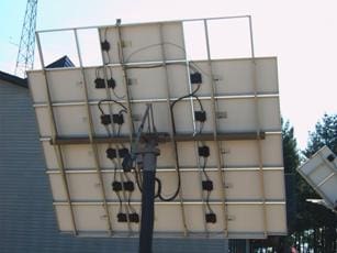
Photovoltaic Module Interconnections

Copper conductors are recommended for almost all photovoltaic system wiring. Copper conductors have lower voltage drops and better resistance to corrosion than other types of comparably sized conductor materials. Aluminum or copper-clad aluminum wires can be used in certain applications, but the use of such cables is not recommended- particularly in dwellings.
All wire sizes presented in this guide refer to copper conductors. The NEC requires 12 AWG (American Wire Gage) or larger conductors to be used with systems under 50 volts. Article 690 ampacity calculations yielding a smaller conductor size might override Article 720 considerations, but some inspectors are using the Article 720 requirement for dc circuits [690.3].
The Code has little information for conductor sizes smaller than 14 AWG, but Section 690.31(D) provides some guidance. Many listed PV modules are furnished with attached 14 AWG conductors.
Single-conductor, Type UF (Underground Feeder—Identified (marked) as Sunlight Resistant), Type SE (Service Entrance), or Type USE/USE-2 (Underground Service Entrance) cables are permitted for module interconnect wiring. Type UF cable must be marked “Sunlight Resistant” when exposed outdoors as it does not have the inherent sunlight resistance found in SE and USE conductors [UL Marking Guide for Wire and Cable].
Unfortunately, single-conductor, stranded, UF sunlight-resistant cable is not readily available and may have only a 60°C temperature rating. This 60°C rated insulation is not suitable for long-term exposure to direct sunlight at temperatures likely to occur near PV modules. Such wire has shown signs of deterioration after four years of exposure. Temperatures exceeding 60°C normally occur in the vicinity of the modules; therefore, conductors with 60°C insulation cannot be used.
Stranded wire is suggested to ease servicing of the modules after installation and for durability. The widely available Underground Service Entrance Cable (USE-2) is suggested as the best cable to use for module interconnects. When manufactured to the UL Standards, it has a 90°C temperature rating and is sunlight resistant even though not commonly marked as such. The “-2” marking indicates a wet-rated 90°C insulation, the preferred rating. Additional markings indicating XLP or XLPE (cross-linked polyethylene) and RHW-2 (90°C insulation when wet) ensure that the highest quality cable is being used [Tables 310.13, 16, and 17].

Wired Photovoltaic Modules
An additional marking (not required) of “Sunlight Resistant” indicates that the cable has passed an extended UV exposure test over that normally required by USE-2. USE-2 is acceptable to most electrical inspectors. The RHH and RHW-2 designations frequently found on USE-2 cable allow its use in conduit inside buildings. USE or USE-2 cables, without the other markings, do not have the fire-retardant additives that SE and RHW/RHW-2 cables have and cannot be used inside buildings.
If a more flexible, two-conductor cable is needed, electrical tray cable (Type TC) is available but must be supported in a specific manner as outlined in the NEC [336 and 392]. TC is sunlight resistant and is generally marked as such.
Although sometimes used (improperly) for module interconnections, SO, SOJ, and similar flexible, portable cables and cordage may not be sunlight resistant and are not approved for fixed (non-portable) installations [400.7, 8].
The temperature derated ampacity of conductors at any point must generally be at least 156% of the module (or array of parallel-connected modules) rated shortcircuit current at that point [690.8(A), (B)].

What Do You Need To Know When Connecting Solar Electric System to the Utility Grid

n the past, most homes with solar electric systems were not connected to the local utility grid. It made sense to install solar electric systems in areas without easy assess to the power grid, where the option of extending a power line from the grid might cost tens of thousands of dollars.
In recent years, however, the number of solar-powered homes connected to the local utility grid has increased dramatically. These “grid-connected” buildings have solar electric panels or “modules” that provide some or even most of their power, while still being connected to the local utility. Owners of grid-connected homes can choose to supply a portion of their energy with solar energy, using the utility for power during the night or on cloudy days. Because of the up-front costs of installing a solar electric system, many of these homeowners initially install systems that meet about one quarter to one-half of their energy use.
Solar electric systems sometimes produce more electricity than your home needs. This extra electricity is either stored in batteries or fed into the utility grid. Homeowners can be given credit by their local power companies for the electricity produced at their homes through “net metering” programs.

Net metering

Simple scheme of connecting solar electric system to the grid

Grid-connected systems generally use a billing process called “net metering” or “net billing”. In this process, any energy generated by the solar modules that your home does not use immediately is sent to the utility grid.
However, when the solar electric system is producing less power than is needed, you can draw additional power from the grid. If your system is connected to the grid through a single electric meter, your meter can actually run backwards as you contribute excess energy to the utility.
The excess electricity is being credited to you at the same retail rate as the electricity you use from the utility. Your utility may require the use of two meters—one that meters your consumption of energy from the grid and the other that meters your contribution to the grid. In this case, your solar-generated excess energy could be credited at the retail rate or possibly at a lower wholesale rate, depending on the utility.
In addition, some utilities bill their customers according to a “time-of-use” rate system. Under this system, customers are billed at a higher rate during certain times of the day, such as during the sunniest daytime hours of summer when air conditioners are working at their peak. If this is the case with your utility, you may be able to “trade” your excess energy to the utility at these same rates.
You can therefore benefit from the fact that your solar electric modules produce the most power during those sunny summer days. When you need power from the utility during the off-peak periods, such as in the evening, the rate is usually lower. If you choose to have a grid-connected solar electric system, and your system produces enough energy in any given month so that you do not have to draw from the grid, you may still receive a small monthly bill. This is because many utilities charge monthly fees for meter reading. Again, check with your local utility.

Connecting to the grid

One of the most important steps in purchasing a grid-connected solar electric system is choosing a provider with experience. A good provider will also have a properly licensed electrical contractor, have enough years of experience to have demonstrated an ability to work with customers, and be able to compete effectively with other firms.
A good provider should be familiar with your local utility’s regulations on interconnection requirements. If your provider is not familiar with these requirements, check with your local utility, state energy office, or state or local Public Utility Commission for details.
Your solar electric provider should supply you with everything you need to run your system, including a specific type of inverter for grid-connected systems, batteries (if you want backup power), and a special electric meter. As mentioned already, some utilities require you to have one electric meter that runs both forward and backward. Other utilities require two separate meters: one for incoming power you receive, and one for power you generate that goes back into the system. These meters are sometimes paid for by the utility, but may be part of your provider’s price for the system.
As part of the installation of your solar electric system, you will need to sign an interconnection agreement with the utility company. Your solar electric provider may be able to handle the negotiations and paperwork with the utility, but this contractual agreement is between you and your local utility. Be sure to read the fine print in this agreement, which may differ considerably from one utility to another. It could range from a short one-page statement to a lengthy booklet. In either case, the fine print may contain references to liability issues that you will want to fully understand before signing the contract.
Also, be sure to speak with your homeowner’s insurance provider, because the solar electric system itself will need to be added to your policy. In many cases, you may have to add a rider to your policy for the grid connected system.

Surge protection of cells and inverter – DC side

Application principle

Surge protection of cells and inverter - DC side
ABB - Photovoltaic protection
Providing power with photovoltaic solar panels is tremendously interesting in the context of renewable energy sources, as regards economical LV photovoltaic systems connected to the public electricity network.
Because of their exposition , frequently in isolated sites and of the extended surface of photovoltaic systems (PV), lightning strikes are a major components in the risk to be assumed, both for the direct effect of lightning on the structures, and of the surge overvoltages on the installation. Cells are generally associated with inverters.
The lightning group of ABB has developed a specific Din Rail product to protect DC side of cells and inverters against surge in power plant or residential application. In case of indirect surge , the cells, their electronic components and semi-conductors in the inverters which are essential and expensive equipment could be damaged. The reason is because the electronic components can not support the high value of over voltage.

Detailed description
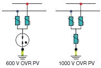
Combination of MOV-MOV (Metal Oxyd Varistor) or MOV-spark gap 
With the combination of MOV-MOV (Metal Oxyd Varistor) or MOV-spark gap, the overvoltage will be limited at the value of the voltage protection level of the ABB OVR surge protector.
Our surge protector, as recommended in standards and guides, insure all protections (between + and -, +and Ground and – and Ground).
On each surge arrester, as option, an available auxiliary contact will inform the end life status to ensure a maximum efficiency.

One easy solution

With this solution, many cells in power plant and residential application have been protected. Thanks to lightning protection group of ABB because for all kind of power in the installation ABB has a solution. If you don’t protect your cells, in case of several big surges, your cells will be completely damaged and in case of many small surges without visual damages for you, your efficiency will go down over the years.
You should use a surge protection to have a better return on investment.
Example of typical installation

You should also check with your insurance company if in your contract, a surge protection is required to be insured at 100%.

Technical Data

  • Official name: Surge Protection Device (SPD)
  • IEC 61643-1: International standard for surge protective devices connected to low-voltage power distribution systems
  • Surge arresters Type 1: for buildings protected by lightning rods
  • High capability: 15 kA up to 100 kA in 10/350
  • Low protection level: 1,8 kV (electronic triggering)
  • Very small size compared to performance.
  • Surge arresters Type 2: OVR SPD’S – in the other situations or in coordination with Type 1
  • Pluggable lightning arresters
  • Safety reserve
  • Optical monitoring bloc
  • Modular range
  • Surge arresters Type 3 – to protect equipment against small over voltages or in coordination with Type 2
SOURCE: ABB – Photovoltaic application, Surge protection Protection of cells & Inverter DC side

Overview of solar panel types

There are three common technologies used in solar panels, all of which are based on the common element silicon, which makes up a large proportion of the earth.

Monocrystalline cells

Mono Crystalline Solar Panels
Monocrystalline cells are made from a thin slice or wafer cut from a single large crystal of silicon. The cells are then doped and the fine current collecting wires printed on or in the surface of the cell.
Generally monocrystalline cells have the highest efficiency, but this comes at a price. This type of cell takes more energy to make than any other, and so has a greater energy payback period, though this is usually still within five years. A number of manufacturers make monocrystalline panels, including BP Solar and Sharp Solar.

Polycrystalline cells

Polycrystalline solar panel
Polycrystalline cells are made from thin wafers of silicon cut from a large cast billet. The billet is not a large single crystal, but many crystals clumped together, hence the name.
Polycrystalline cells are usually slightly less efficient than moncrystalline cells, but because they are square, can be fitted into the rectangular frame of a solar panel with high space efficiency, although polycrystalline panels are still slightly larger than monocrystalline panels of the same rating. Polycrystalline cells must also have current collecting grids printed onto them. Kyocera panels use this cell technology, as do many other panels.

Amorphous/thin film panels

Amorphous solar panels
Amorphous/thin film panels involve deposition of very thin films of silicon or other materials directly onto a substrate such as glass or stainless steel. This technique produces a cell with a lower efficiency than the cut wafer varieties, but has the advantage of eliminating the need for inter-cell connections.
Uni-Solar makes triple junction, nine-layer thin-film amorphous panels with a much higher efficiency than the older types. The layers of silicon are deposited directly onto a stainless steel substrate and are then coated in a flexible plastic protective layer. There are now a number of manufacturers of thin-film panels, including Uni- Solar, Kaneka and Schott Solar.

Comparison

Panels made from polycrystalline cells are the most common and cheapest. (Typically BP, Solarex, Sharp and Kyocera). Their conversion efficiency 13% to 15% (sunlight to electricity). However, under elevated temperatures of 50° C panel temperature, the efficiency drops by around 20%.
Panels made from monocrystalline cells are used in high reliability applications such as telecommunications and remote power. (Typically BP, Siemens and ECO-CAMPER). Their conversion efficiency is typically 14-17.5% (higher than the polycrystalline cells). However, at elevated temp, the efficiency only drops by 10-15% so they are more consistent in output.
Panels made from amorphous cells have been used in portable items for many years (UniSolar). Their conversion efficiency of sunlight to electricity is 5-7%, about half that of the other panels but unlike the other types, their output does not decrease in elevated temperatures.
Panels made thin film cell CIGS technology. (Copper, Indium, Gallium, diSelenide) are flexible, durable, and provide slightly higher efficiency than other flexible solar cells. (SUNLINQ, Global Solar, P3). Typical sizes less than 60W.They can be mounted to curved surfaces and any backpack, tents or jackets.

Friday 29 March 2013

Long history of solar energy

As with hydropower, solar energy has a long history. Many pre-historic cultures used it to warm their dwellings, dry their clothes, and cure their food. The importance of solar energy was so great that most cultures revered the Sun and created rudimentary observatories to track its location in the sky (ex. Stonehenge).
Some found solar energy so important that they even codified its power in their laws.
Ancient Romans relied so heavily on solar energy to heat their homes and bathhouses that it was illegal to build a house or dwelling so tall so as to block the sunlight of any neighbor.
Ancient Rome was not the only culture to rely heavily on the Sun for energy. The Anasazi cliff dwellers of the ancient American Southwest also used their knowledge of the Sun’s motion in the sky to heat and cool their homes. They built their dwellings into the sides of cliffs that faced the south. In the winter, sunlight was able to shine on their homes, while the cliffs protected their homes from cold northern winds that might blow.
In the summer, the overhangs from the cliffs shaded their homes from the Sun, and thus made it cooler.
Just as with hydropower, solar energy began to wane as a conventional energy source as fossil fuels and nuclear energy became cheap and reliable. The expense and variability of using sunlight has relegated its use to unusual situations where fossils fuels and nuclear energy are not available or where they are prohibitive to use or maintain. A perfect example of this is on satellites, which need energy to power all on board computers and instrumentation. Using fossil fuels to power a satellite over its lifetime would require quantities of oxygen and fuel that would be prohibitive to shoot into orbit. Nuclear material would be fine for powering the spacecraft, but would become very problematic when the satellites life was over and it came crashing back to Earth.
An example of solar energy that is closer to home are interstate call boxes that are in remote locations. Rather than spending a lot of money to run telephone and electric lines out to these call boxes, one can use a solar panel equipped with a battery and a cell or satellite phone.
Outside of these few types of uses, though, solar energy has seen limited usage. In fact, in some parts of the U.S., the use of solar energy is prohibited. Covenants in some modern subdivisions that have homeowners associations actually forbid the use of solar panels or clotheslines for drying clothes. The reason for this is one of aesthetics: using solar systems can look “ugly” and hurt property values. Some states, such as California, have actually written state laws that prohibit subdivision convents from doing this.
I’m pretty worried about this folks that bring this kind of laws that forbid use of solar energy! People still has to learn that energy is not free, but is everywhere, and sometimes clean, but not pretty.
SOURCE: ESA21 Environmental Science Activities for the 21st Century

Want to live and use energy on Mars? Why not?

The problem of energy accessibility and production on Mars is one of the three main challenges for the upcoming colonisation of the red planet. The energetic potential on its turn is mainly dependent on the astrophysical characteristics of the planet. A short insight into the Mars environment is thus the compulsory introduction to the problem of energy on Mars.
The present knowledge of the Martian environment is the result of more than two centuries of attentive observation on its astronomical appearance and, more recently, on its on-site astrophysical features. Recent surface measurements of Martian geology, meteorology and climate had fixed the sometime-unexpected image of a completely desert planet.
Mars is one of the most visible of the seven planets within the solar system and thus for its discovery cannot be dated, still the interest for Mars is old. It was easily observed from the ancient times by necked eye and the peculiar reddish glance of the planet had induced the common connection of the poor planet with the concept of war. The god of war and the planet that inherited his name had provoked, still from antiquity, curiosity and disputes on the most diverse themes. These disputes are at a maximum right now regarding the habitability of Mars.
The red planet owes his color to still unexplained causes, where a yet undisclosed chemistry of iron oxides seems to be the main actor. The visit card of Mars is fast increasing in the quantity of data and is now quite well known (Bizony, 1998), as we observe from the description that follows.

Mars as seen before the space age

As far as the knowledge of the solar system has gradually extended, from optical, ground-based observations to the present astrophysical research on site, Mars appears as the fourth planet as starting from the Sun. The reddish planet of the skies, nicely visible by necked eyes, has attracted the most numerous comments during the time regarding the presence of life on an extra terrestrial planet.
With all other eight planets, except for Pluto-Charondoublet, Mars aligns to a strange rule by orbiting the Sun at a distance that approximates amultiple of √2 from that of the Earth. This means that the rough 149.6 mil km of the Earth semi-major axis is followed by a rough 212 mil km for Mars. In fact there are 227.92 mil km at mean from the center of Sun. The power rule of  Titius-Bode, modified several times, but originally described as a =  (4 + 3 x sgn n x 2n-1) / 10 | n = 0,9 gives a better distribution.
Table 1. Mars within Titius-Bode’s rule (astronomical units)
PlanetnTitius-Bode ruleActual semi-major axis
Mercury00.40.39
Venus10.70.72
Earth21.01.00
Mars31.61.52
Asteroids42.82.80
Jupiter55.25.20
Saturn610.09.54
Uranus719.619.20
Neptune/Pluto838.830.10/39.20
Sedna977.275.00
It is immediately seen that the primary solar radiation flux is roughly two times smaller for Mars than it is for Earth. More precisely, this ratio is equal to 2.32. This observation for long has suggested that the climate on Mars is much colder than the one on Earth. This has not removed however the belief that the red planet could be inhabited by a superior civilization. Nevertheless, beginning with some over-optimistic allegations of Nicolas Camille Flammarion (Flamarion, 1862) and other disciples of the 19-th century, the planet Mars was for a century considered as presenting a sort of life, at least microbial if not superior at all. The rumor of Mars channels is still impressing human imagination.
When estimates begun to appear regarding the Martian atmosphere and figures like 50 mbar or 20 mbar for the air pressure on Martian ground were advanced (Jones 2008), a reluctant wave of disapproval has been produced. It was like everybody was hoping that Mars is a habitable planet, that we have brothers on other celestial bodies and the human kind is no more alone in the Universe. As more data were accumulating from spectroscopic observations, any line of emission or absorption on Mars surface was immediately related to possible existence of biological effects.
Even during the middle 20-th century the same manner was still preserving. In their book on “Life in the Universe” Oparin and Fesenkov are describing Mars in 1956 as still a potential place for biological manifestations (Oparin & Fesenkov, 1956).The following two excerpts from that book are relevant, regarding the claimed channels andbiological life on Mars: “…up to present no unanimous opinion about their nature is formed, although nobody questions that they represent real formations on the planet (Mars)…” and at the end of the book “On Mars, the necessary conditions for the appearance and the development of life were always harsher than on Earth. It is out of question that on thisplanet no type of superior form of vegetal or animal life could exist.
However, it is possiblefor life, in inferior forms, to exist there, although it does not manifest at a cosmic scale.

Reasons and costs for terraforming Mars

Thicken Mars’ atmosphere, and make it more like Earth’s. Earth’s atmosphere is about 78% Nitrogen and 21% Oxygen, and is about 140 times thicker than Mars’ atmosphere. Since Mars is so much smaller than Earth (about 53% of the Earth’s radius), all we’d have to do is bring about 20% of the Earth’s atmosphere over to Mars. If we did that, not only would Earth be relatively unaffected, but the Martian atmosphere, although it would be thin (since the force ofgravity on Mars is only about 40% of what it is on Earth), would be breathable, and about the equivalent consistency of breathing the air in Santa Fe, NM.
So that’s nice; breathing is good. Mars needs to be heated up, by a lot, to support Earth-like life. Mars is cold. Mars is damned cold. At night, in the winter, temperatures on Mars get down to about -160 degrees! (If you ask, “Celcius or Fahrenheit?”, the answer is first one, then the other.) But there’s an easy fix for this: add greenhouse gases. This has the effect of letting sunlight in, but preventing the heat from escaping. In order to keep Mars at about the same temperature as Earth, all we’d have to do is add enough Carbon Dioxide, Methane, and Water Vapor to Mars’ atmosphere.Want to know something neat? If we’re going to move 20% of our atmosphere over there, we may want to move 50% of our greenhouse gases with it, solving some of our environmental problems in the process.
These greenhouse gases would keep temperatures stable on Mars and would warm the planet enough to melt the ice caps, covering Mars with oceans. All we’d have to do then is bring some lifeforms over and, very quickly, they’d multiply and cover the Martian plane tin life. As we see on Earth, if you give life a suitable environment and the seeds forgrowth/regrowth, it fills it up very quickly. So the prospects for life on a planet with an Earth-like atmosphere, temperature ranges, and oceans are excellent. With oceans and an atmosphere, Mars wouldn’t be a red planet any longer.
It would turn blue like Earth! This would also be good for when the Sun heated up in several hundred million years, since Mars will still be habitable when the oceans on Earth boil. But there’s one problem, Mars has that Earth doesn’t, that could cause Mars to lose its atmosphere very quickly and go back to being the desert wasteland that it is right now: Mars doesn’t have a magnetic field to protect it from the Solar Wind. The Earth’s magneticfield, sustained in our molten core, protects us from the Solar Wind. Mars needs to be given a magnetic field to shield it from the Solar Wind. This can be accomplished by either permanently magnetizing Mars, the same way you’d magnetize a block of iron to make a magnet, or by re-heating the core of Mars sufficiently to make the center of the planet molten. In either case, this allows Mars to have its own magnetic field, shielding it from the Solar Wind (the same way Earth gets shielded by our magnetic field) and allowing it to keep its atmosphere, oceans, and any life we’ve placed there. But this doesn’t tell us how to accomplish these three things. The third one seems to us to be especially difficult, since it would take a tremendous amount of energy to do. Still, if you wanted to terraform Mars, simply these three steps would give you a habitable planet.
The hypothetical process of making another planet more Earth-like has been called terraforming, and terraforming Mars is a frequently mentioned possibility in terraforming discussions. To make Mars habitable to humans and earthly life, three major modifications arenecessary. First, the pressure of the atmosphere must be increased, as the pressure on the surface of Mars is only about 1/100th that of the Earth.
The atmosphere would also need the addition of oxygen. Second, the atmosphere must be kept warm. A warm atmosphere wouldmelt the large quantities of water ice on Mars, solving the third problem, the absence of water.
Terraforming Mars by building up its atmosphere could be initiated by raising the temperature, which would cause the planet’s vast CO2 ice reserves to sublime and become atmospheric gas.
The current average temperature on Mars is −46 °C (-51 °F), with lows of −87 °C (-125 °F), meaning that all water (and much carbon dioxide) is permanently frozen.
The easiest way to raise the temperature seems to be by introducing large quantities of CFCs (chlorofluorocarbons, a highly effective greenhouse gas) into the atmosphere, which couldbe done by sending rockets filled with compressed CFCs on a collision course with Mars. After impact, the CFCs would drift throughout Mars’ atmosphere, causing a greenhouse effect,which would raise the temperature, leading CO2 to sublimate and further continuing thewarming and atmospheric buildup. The sublimation of gas would generate massive winds,which would kick up large quantities of dust particles, which would further heat the planet through direct absorption of the Sun’s rays. After a few years, the largest dust storms would subside, and the planet could become habitable to certain types of algae and bacteria, whichwould serve as the forerunners of all other life. In an environment without competitors and abundant in CO2, they would thrive. This would be the biggest step in terraforming Mars.

Conclusion

The problem of creating a sound source of energy on Mars is of main importance and related to the capacity of transportation from Earth to Mars, very limited in the early stages of Mars colonization, and to the capacity of producing the rough materials in situ. Consequently the most important parameter that will govern the choice for one or another means of producing energy will be the specific weight of the powerplant. Besides then uclear sources, that most probably will face major opposition for a large scale use, the onlyapplicable source that remains valid is the solar one. As far as the solar flux is almost fourtimes fainter on Mars than on Earth, the efficiency of PVC remains very doubtfull, although it stands as a primary candidate.
This is why the construction of the gravity assisted air accelerators looks like a potential solution, especially when rough materials will be availableon Mars surface itself. The thermal efficiency of the accelerator for producing a high power draught and the propulsion of a cold air turbine remains very high and attractive. The largearea of the solar reflector array is still one of the basic drawbacks of the system, that only could be managed by creating very light weight solar mirrors, but still very stiff to withstandthe winds on Mars surface.

SOURCE: Potential of the Solar Energy on Mars – Dragos Ronald Rugescu and Radu Dan Rugescu

How solar collectors works?

Solar collector
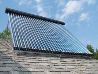
Typical solar collector installed on the roof
Solar energy (solar radiation) is collected by the solar collector’s absorber plates. Selective coatings are often applied to the absorber plates to improve the overall collection efficiency.
A thermal fluid absorbs the energy collected. There are several types of solar collectors to heat liquids. Selection of a solar collector type will depend on the temperature of the application being considered and the intended season of use (or climate).
The most common solar collector types are: unglazed liquid flatplate collectors; glazed liquid flat-plate collectors; and evacuated tube solar collectors.

Unglazed liquid flat-plate collectors

Unglazed liquid flat-plate collectors, as depicted in Figure 8, are usually made of a black polymer. They do not normally have a selective coating and do not include a frame and insulation at the back; they are usually simply laid on a roof or on a wooden support. These low-cost collectors are good at capturing the energy from the sun, but thermal losses to the environment increase rapidly with water temperature particularly in windy locations.
As a result, unglazed collectors are commonly used for applications requiring energy delivery at low temperatures (pool heating, make-up water in fish farms, process heating applications, etc.); in colder climates they are typically only operated in the summer season due to the high thermal losses of the collector.
Figure 8: System Schematic for Unglazed Flat-Plate Solar Collector.


Glazed liquid flat-plate collectors

Figure 9: System Schematic for Glazed Flat-Plate Solar Collector.

In glazed liquid flat-plate collectors, as depicted in Figure 9, a flat-plate absorber (which often has a selective coating) is fixed in a frame between a single or double layer of glass and an insulation panel at the back.
Much of the sunlight (solar energy) is prevented from escaping due to the glazing (the “greenhouse effect”).
These collectors are commonly used in moderate temperature applications (e.g. domestic hot water, space heating, year-round indoor pools and process heating applications).

Evacuated tube solar collectors

Evacuated tube solar collectors, as depicted in Figure 10, have an absorber with a selective coating enclosed in a sealed glass vacuum tube.
They are good at capturing the energy from the sun; their thermal losses to the environment are extremely low. Systems presently on the market use a sealed heat-pipe on each tube to extract heat from the absorber (a liquid is vaporised while in contact with the heated absorber, heat is recovered at the top of the tube while the vapour condenses, and condensate returns by gravity to the absorber).
Figure 10: System Schematic for Evacuated Tube Solar Collector


Evacuated collectors are good for applications requiring energy delivery at moderate to high temperatures (domestic hot water, space heating and process heating applications typically at 60°C to 80°C depending on outside temperature), particularly in cold climates.

Wednesday 27 March 2013

Are renewable resources practical?

Are renewable resources practical?


While few people disagree that renewable energy is a good idea, most also recognize there are two practical barriers to implementation on a wide scale.
First, all renewable energy sources, except for hydro-electric power, cost from two to five times what fossil fuel and nuclear energy costs, even when their “free” fuel costs are factored into the analysis. Many, first-world countries could afford the higher cost, thus decreasing their emissions and fossil fuel use at some slight reduction in spending on other items. But lowcost power is essential to the industrial processes that provide the basis for the world economy, not just that of rich nations.
And among the first “other items” for which spending would be reduced would no doubt be charity and aid given to developing nations. In addition, those third-world countries cannot improve their standards of living unless plentiful, cheap power is available in growing amounts.
As a result, while renewable energy costs will likely continue to decrease at a slow pace as technology improves, only cost competitiveness will bring about big changes and thus widespread usage.

Site requirements

Second, all renewable energy sources have some type of special site requirements that make them suitable for only some parts of the world and some locations. Many renewable methods, such as hydro, geothermal, and wind, can be used only at a relatively small number of locations, where the water, geological, or wind energy can be found.
The power must be generated there, regardless of where it will ultimately be used. Considerable land must then be cleared and devoted to high-voltage transmission lines to get the power to where it is consumed – creating another type of significant environmental impact.
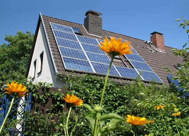
Solar powered house
Solar powered house

Even solar power has only regional applicability. While theoretically, solar thermal and photovoltaic power will work anywhere, both are practical only in locations where the sun shines a good portion of the day. Near the equator, solar thermal power plants receive nearly 12 useful hours of sunlight daily. But beyond 50 degrees latitude north or south, there are many days of the year when there is simply not enough daylight, leaving energy consumers in need of spending more on some other “backup” supply for those times.
Similarly, biomass plants work only in areas where there is a long growing season. Year-round growing seasons are best, of course, although biomass can also work where the added cost of considerable fuel storage for cut grass and timber is feasible.

Smart Ways to Save Money with Alternative Energy

Save Money With Alternative Energy

Alternative energy is currently a hot button topic. Whether your desire to use alternative energy stems from concern for the environment or a desire to create a healthier home, you will benefit financially from making the switch to alternative energy.
Transitioning to alternative energy can save you a lot of money.
There are numerous changes you can make in your life that will help you utilize alternative energy and take advantage of the savings it provides.

Using Alternative Energy in Your Home

One of the biggest ways to save money is by transitioning to alternative energy sources in your home. In some cases, this is a big investment.
Using traditional energy sources is convenient, but it hands over a lot of your control to your local energy company.
Choosing alternative sources means you have more control over how much you use and, in some cases, how much you pay for energy. Initially, a financial investment may be necessary to get a new system up and running, but in the long run, you will see a big savings.
Heating your home with a pellet stove is a great way to save money with alternative energy.Pellet stoves add the ambiance of a roaring fire to a space, but it also adds a great deal of heat for a reasonable cost. Pellet stoves burn compressed recycled wood pellets and corn. You can buy a 40 pound bag of these alternative fuels for about $3 to $5 and the supply typically lasts 24 to 48 hours. You can also buy the alternative fuels in bulk, creating bigger savings. Homeowners love saving with this method of heating because they are in complete control of their heating.
Solar power is another way to use alternative energy in your home. Solar panels allow you to heat and light your home without relying on an energy company. Panels come in a range of sizes and can be installed professionally or by the homeowner. Prefabricated solar kits allow homeowners to install their own panels and begin saving in as little as a weekend.
The advantage of transitioning to solar energy is the ability to do it gradually. You can upgrade slowly, allowing you to make the money-saving improvements as time allows.

Be Aware of Your Water

Water conservation is one of the easiest ways to save money on energy. Though the water supply in some regions of the world might seem unlimited, it is not. The more water you conserve, the more you are protecting the earth. Using alternative energy and conservation practices helps you save money. It can be as simple as just limiting the amount of water you use on the daily basis.
You can also install water heaters that allow you to heat water without using the traditional multi-gallon tank. This means you are wasting less water and using less gas or electricity to heat the water. There are also less expensive ways to cut back on water usage including repairing leaking faucets, installing low-pressure toilets, limiting baths, and operating water-use appliances only when they are full. You can also invest in appliance brands that offer additional energy savings.

Turn Your Kids Green

The earlier people learn the value of alternative energy, the easier it will be to use those forms of energy later in life. If you can teach your children the value of using alternative energy, it will benefit them their entire lives. They learn to conserve energy when they are young, saving you money in the present. They also turn to alternative energy sources later in life, saving money over the long term.
Teaching kids to use alternative energy is the key to making new forms of energy mainstream. If alternative energy is their reality right from the start, it will not be a challenge for them to adjust to these options later in life.

Be a Conscious Consumer

If you are making responsible choices in regard to alternative energy, you should expect the same from the companies supplying your food and other consumer needs. When shopping, choose companies that use alternative energy in their manufacturing practices. Some of these products cost a little more initially, but many products are healthier when created with alternative energy. In the long run, choosing the greenest option will lead to a healthier life. This means you will cut down on healthcare costs over the course of your lifetime.
Incorporate composting into your lifestyle by using food scraps in your garden. Cut down on the amount of food you throw away by instituting a zero-waste food plan. This means you find a way to use every possible piece of food you bring into your home. You can also incorporate different cooking techniques into your life. The less you run your stove, microwave, and oven, the less energy you use.

Know Your Stuff

Sometimes the most challenging part of using alternative energy is being aware of all of your options. You have a lot of choices when it comes to using alternative energy and it can feel overwhelming when you begin doing your research. Before long, the investments to upgrade to alternative energy might seem budget-breaking and you will be tempted to give up.
There is nothing wrong with taking small steps. Even a little change can make a big difference over time. Try not to feel overwhelmed. One of the benefits of alternative energy is taking control of your lifestyle, so there is no reason to let the process stress you out.
It is also important to understand the indirect ways you can save from using alternative energy. In addition to things like long-term health savings, you can also benefit from tax savings when using alternative energy. Many states, as well as the federal government offer financial benefits to those who commit to using alternative forms of energy.
If you want to make the most of the cost saving benefits by using alternative energy, make sure you understand the tax rewards associated with the upgrades you decide to make.

Solar energy is free, but what does it really cost?

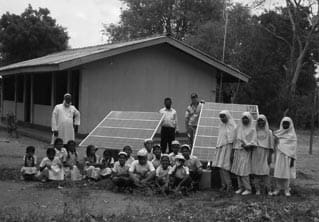
Solar panels powering a rural cultural and drama centre
Solar panels powering a rural cultural and drama centre, near Auroreville, Pondicherri

Solar energy is free, but it’s not cheap” best sums up the major hurdle for the solar industry. There are no technical obstacles per se to developing solar energy systems, even at the utility megaWatt level (e.g., 14 MW utility scale PV system at Nellis AFB or a 64-MW CSP system in Nevada); however, at such large scales a high initial capital investment is required.
Over the past three decades, a significant reduction of the cost of solar products has occurred, without including environmental benefits; yet, solar power is still considered a relatively expensive technology. For small- and medium-scale uses, in some applications, such as passive solar design for homes, the initial cost of a home designed to use solar power is essentially no more than that of a regular home, and operating costs are much less.
The only difference is that the solar-energy home works with the Sun throughout the year and needs smaller mechanical systems for cooling and heating, while poorly designed homes fight the Sun and are iceboxes in the winter and ovens in the summer.
Industrial society and modern agriculture were founded on fossil fuels (coal, oil, and gas). The world will make a gradual shift throughout the twenty-first century from burning fuels to tech-nologies that harness clean energy sources such as sun and wind.As energy demand increases as developing countries modernize and fossil fuel supply constricts, increased fuel prices will force alternatives to be introduced. The cost of technologically driven approaches for clean energy will continue to fall and become more competitive.
Eventually, clean energy technologies will be the inexpensive solution.
As the full effect and impact of environmental externalities such as global warming become apparent, society will demand cleaner energy technologies and policies that favor development of a clean-energy industrial base. By the end of the twenty-first century, clean-energy sources will dominate the landscape.
This will not be an easy or cheap transition for society, but it is necessary and inevitable.

Rural Systems

Rural Pakistani village
Already, solar energy is cost effective for many urban and rural applications. Solar hot-water systems are very competitive, with typical paybacks from 5–7 years as compared to electric hot-water heaters (depending on the local solar resource).
PV systems are already cost competitive for sites that are remote from the electric grid, although they are also popular for on-grid applications as environmental “elitists” try to demonstrate that they are “green.
”However, one should beware of “green-washing” as people and companies install grid-tied PV systems without making efforts to install energy-efficient equipment first. Far more can be achieved through energy conservation than solar energy usage alone for reducing carbon emissions.

The decision to use a solar energy system over conventional technologies depends on the economic, energy security, and environmental benefits expected. Solar energy systems have a relatively high initial cost; however, they do not require fuel and often require little maintenance. Due to these characteristics, the long-term life cycle costs of a solar energy system should be understood to determine whether such a system is economically viable.
Historically, traditional business entities have always couched their concerns in terms of economics. They often claim that a clean environment is uneconomical or that renewable energy is too expensive. They want to continue their operations as in the past because, sometimes, they fear that if they have to install new equipment, they cannot compete in the global market and will have to reduce employment, jobs will go overseas, rates must increase, etc.
The different types of economics to consider are pecuniary, social, and physical. Pecuniary is what everybody thinks of as economics: dollars. Social economics are those borne by everybody and many businesses want the general public to pay for their environmental costs. If environmental problems affect human health today or in the future, who pays? Physical economics is the energy cost and the efficiency of the process. There are fundamental limitations in nature due to physical laws. In the end, the environment and future generations always suffer the corollary of paying now or probably paying more in the future.
An economical analysis should be looking at life cycle costs, rather than at just the ordinary way of doing business and low initial costs. Life cycle costs refer to all costs over the lifetime of the system. Also, incentives and penalties for the energy entities should be accounted for.
What each entity wants is to earn subsidies for itself and penalties for its competitors. Penalties come in the form of taxes and fines; incentives may come in the form of tax breaks, unaccounted social and environmental costs, and also what the government (society) could pay for research and development.
Reference: Solar energy – Renewable energy and the environment – R.Foster

An Overview Of Smart Power Grid


An Overview Of Smart Power Grid

Abstract

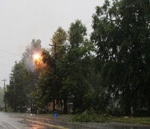
Tree limbs create a short circuit during a storm, typically resulting in a power outage
Figure 1 - Tree limbs create a short circuit during

a storm, typically resulting in a power outage
The present electric grids use the technology of 1970’s. But with the advancement in various concepts of power generation, problems associated with power outages and thefts, and also due to increase in demand, we require a modernized grid to avail all the needs of customers even in the situations of hype, which can be called a “smart grid”.
The smart grid performs various functions such that it increases grid stability, reliability, efficiency and ultimately reduces line losses.
Also the smart grids are designed to allow the two-way processing of electricity from consumers that have distributed generation. Various technologies like sensing and measurement, usage of advanced components are to be used for successful functioning of the grid. In this paper, smart grid, its functions, technologies used in smart grids are discussed.

Introduction to Electric Grid

The electric grid generally refers to all or the smart grid, in a nutshell, is a way to transmit and distribute electricity by electronic means. The electric grid delivers electricity from points of generation to consumers. The electricity delivery network functions via two primary networks: the transmission system and the distribution system. The transmission systems deliver electricity from power plants to distribution substations, while distribution systems deliver electricity from distribution substations to consumers.
The grid also encompasses myriads of local area networks that use distributed energy resources to several loads and/or to meet specific application requirements for remote power, municipal or district power, premium power, and critical loads protection.

Introduction to Smart Grid

Smart grid lacks a standard definition, but enters on the use of advanced of technology to increase the reliability and efficiency of the grid, from transmission to distribution. The Smart Grid is a vision of a better electricity delivery infrastructure.
Smart Grid implementation dramatically increases the quantity, quality, connectivity, automation and Coordination between the suppliers, consumers and networks, and use of data available from advanced sensing, computing, and communications hardware and software.
In addition to being outdated, power plants and transmission lines are aging, meaning they have difficulty handling current electricity needs, while demand may not be reduced any time, but it can still be increasing continuously. One solution could be to add more power lines, but the aging system would still be overwhelmed.
So instead of a quick fix, a more reliable, permanent solution is needed. Perhaps the most fundamental aspect of transitioning to a smarter electricity system is the smart meter.

Why Modernization of Electric Grid is required?

The major driving forces to modernize current power grids can be divided in four, general categories:
  • Increasing reliability, efficiency and safety of the power grid.
  • Enabling decentralized power generation so homes can be both an energy client and supplier (provide consumers with interactive tool to manage energy usage).
  • Flexibility of power consumption at the client’s side to allow supplier selection (enables distributed generation, solar, wind, and biomass).
  • Increase GDP by creating more new, green collar energy jobs related to renewable energy industry manufacturing, plug-in electric vehicles, solar panel, and wind turbine generation, energy conservation and construction.
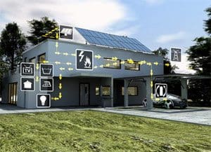
Smart grid delivery
Smart grid delivery


Smart Grid Functions

The integrated system of the smart grid has two scopes.
One scope is transmission monitoring and reliability and includes the following capabilities:
  • Real time monitoring of grid conditions.
  • Improved automated diagnosis of grid disturbances, and better aids for the operators who must respond to grid problems.
  • Automated responses to grid failure that will isolate disturbed zones and prevent or limit cascading blackouts that can spread over a wide area.
  • “Plug and play” ability to connect new generating plants to the grid, reducing the need for the time consuming interconnection studies and physical upgrades.
  • The automatic restoration of power would be accomplished by a combination of sensors, computer analysis and advanced substation components, as well as by the ability to reroute power to outage locations.
  • Enhancing ability to manage large amounts of solar and wind power.
The second scope is consumer energy management:
  • At a minimum, the ability to signal homeowners and businesses that power is expensive and/or tight in supply. This can be done, via special indicators or through web browsers or personal computer software. The expectation is that the customer will respond by reducing its power demand.
  • The next level of implementation would allow the utility to automatically reduce the consumer’s electricity consumption when power is expensive or scarce. This would be managed through the link between the smart meters and customer’s equipment or appliances.
  • The smart grid system would automatically detect distribution line failures, identify the specific failed equipment, and help determine the optimal plans for dispatching crews to restore service. The smart grid would automatically attempt to isolate failures to prevent local blackouts to spread over that area.
  • The smart grid would make it easier to install distributed generation such as rooftop solar panels, and to allow “net metering”, a rate making approach that allows operators of distributed generators to sell surplus power to utilities. The smart grid would also manage the connection of millions of plug-in hybrid electric vehicles into the power system.
Hence the functions of smart grid can be summarized into the following terms as selfhealing, consumer participation, resist attack, high quality power accommodate generation options, enable electricity markets, optimize assets, enable high penetration of intermittent generation options.

Technology- Initial Focus

Smart Grids rely on information technology advancements across telecommunications and operations. Utilities apply these technologies both to grid operations – transmission and distribution wires and associated equipment and to the customer site-meters, customer owned energy technology equipment and appliances, and home area networks (HANs).

Wires

Smart grid wires
High temperature superconductor (HTS) wire enables power transmission and distribution cables with three to five times the capacity of conventional underground AC cables and up to ten times the capacity of DC cables. Fault current management capability when using Fault Blocker cable systems.

Wires-focused Smart Grid projects commonly involve:
  • One of the components to smart grid would be the replacement of the aging power lines with high-temperature superconducting lines.
  • The new wires could be installed underground to avoid cluttering up the already congested cityscapes.
  • New telecommunications and operational (sense and control) technologies: These improve delivery performance and resilience.
  • New sensor and control technologies. These, when combined with distributed intelligence, make it possible to report and resolve grid issues in real time (self healing).
  • Transmission and distribution intelligent electronic devices. These alert operators, automatically respond to problems, and integrate generation from renewable resources.

Sensing and Measurement

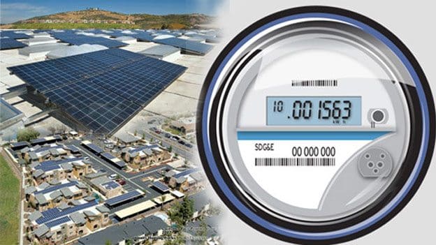
 Smart Grid - Advanced Metering Infrastructure (AMI)
Smart Grid - Advanced Metering Infrastructure (AMI)


Core duties are evaluating congestion and grid stability, monitoring equipment health, energy theft prevention, and control strategies support. Technologies include smart meters, sensing systems, advanced switches and cables, digital protective relays etc… In all these, smart meters play a vital role.
In Smart Metering, an Advanced Metering Infrastructure (AMI) of interval meters and two-way communications systems serves as a gateway for utility/customer interaction. Smart Metering has the potential to reduce both customer and utility costs.
If you take a look at your current electricity meter, you will see that it is very mechanical, humming along blindly, waiting to be read by a technician, to determine the amount of electricity used in a given month, at the end of which you receive a bill. A smart meter utilizes what is known as real-time monitoring (RTM). A display lets the consumer know how much electricity is used and even when it is less expensive to use it.
“Studies have shown that when people are made aware of how much power they are using, they reduce their use by about 7%.” A smart grid also prevents the entire system from becoming overloaded, lessening the chance for a power outage.

Advanced Components

Innovations in superconductivity, fault tolerance, storage, power electronics, and diagnostics components are changing fundamental abilities and characteristics of grids.
Technologies within these broad R&D categories include: flexible alternating current transmission system devices, high voltage direct current, first and second generation superconducting wire, high temperature superconducting cable, distributed energy generation and storage devices, composite conductors, and “intelligent” appliances.

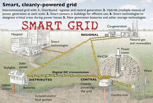
Renewable Energy and the Smart Grid

Renewable Energy and the Smart Grid


The smart grid can be seen as an alternative energy source, certainly a change from the current way of doing things. In addition to rerouting electricity, the smart grid would be able to fill in the gaps of these alternative energy power sources. One way this could be accomplished, surprisingly enough, is with another alternative energy technology – the electric car, specifically, the plug-in electric hybrid (PHEV).
This would work through the concept of energy storage, in the case of the PHEV, specifically referred to as V2G or vehicle to grid. This use of alternative energy sources, like wind and solar reduces the nation’s dependence on foreign oil and helps keep pollution from car exhaust and power plants to a minimum.

Other Technologies

Integrated communications will allow for real-time control, information and data exchange to optimize system reliability, asset utilization, and security.

Conclusion

The major source of energy for human beings is electricity. Without electricity, no technology or science could have been possibly developed. But there are many problems associated with effective functioning of the electric grids which cause a serious loss of power and may even create severe scarcity in future. Also, the latest advancements in generation of electricity from renewable sources also require a means for effective utilization.
So, keeping in view of these, for better performance of the grid, smart grids should be developed all over the world So that we have a more transparent, reliable system that allows consumers to save money and utility companies to more accurately control electricity.
Thus Smart Grid technology paves way for increased utilization of green power.