The Hybrid HVDC Breaker by ABB - The hybrid design has negligible conduction losses, while preserving ultra-fast current interruption capability.
Content
- Introduction to HHVDC
- How does Hybrid HVDC Breaker work? (VIDEO)
- Hybrid HVDC Breaker Construction
- Proactive control
- Prototype Design Of The Hybrid HVDC Breaker
- Comparison/Summary
Introduction
The advance of voltage source converter-based (VSC) high-voltage direct current (HVDC) transmission systems makes it possible to build an HVDC grid with many terminals.
Compared with high-voltage alternating current (AC) grids, active power conduction losses arerelatively low and reactive power conduction losses are zero in an HVDC grid.
This advantage makes an HVDC grid more attractive.
However, the relatively low impedance in HVDC grids is a challenge when a short circuit fault occurs, because the fault penetration is much faster and deeper.
Consequently, fast and reliable HVDC breakers are needed to isolate faults andavoid a collapse of the common HVDC grid voltage.
Furthermore, maintaining a reasonable level of HVDC voltage is a precondition for the converter station to operate normally. In order to minimize disturbances in converter operation, particularly the operation of stations not connected to the faulty line or cable, it is necessary to clear the fault within a few milliseconds.
How does Hybrid HVDC Breaker work? (VIDEO)
Hybrid HVDC Breaker Construction
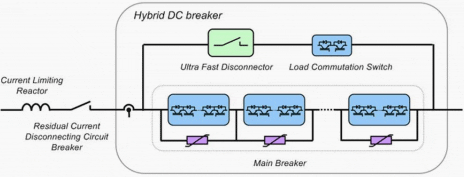
The hybrid HVDC breaker consists of an additional branch, a bypass formed by asemiconductor-based load commutation switch in series with a fast mechanical disconnector.
The main semiconductor-based HVDC breaker is separated into several sections with individual arrester banks dimensioned for full voltage and current breaking capability, whereas the load commutation switch matches lower voltage and energy capability.
After fault clearance, a disconnecting circuit breaker interrupts the residual current and isolates the faulty line from the HVDC grid to protect the arrester banks of the hybrid HVDC breaker from thermal overload.
 |
| Figure 1 - Hybrid HVDC breaker main components |
During normal operation the current will only flow through the bypass, and the current in the main breaker is zero.
When an HVDC fault occurs, the load commutation switch immediately commutates the current to the main HVDC breaker and the fast disconnector opens. With the mechanical switch in open position, the main HVDC breaker breaks the current.
The mechanical switch isolates the load commutation switch from the primary voltage across the main HVDC breaker during current breaking.
Thus, the required voltage rating of the load commutation switch is significantly reduced.
A successful commutation of the line current into the main HVDC breaker path requires a voltage rating of the load commutation switch exceeding the on-state voltage of the main HVDC breaker, which is typically in the kV range for a 320 kV HVDC breaker.
This result in typical on-state voltages of the load commutation switch is in the range of several volts only.
The transfer losses of the hybrid HVDC breaker concept are thus significantly reduced to a percentage of the losses incurred by a pure semiconductor breaker.
The mechanical switch opens at zero current with low voltage stress, and can thus be realized as a disconnector with a lightweight contact system. The fast disconnector will be exposed to the maximum pole-to-pole voltage defined by the protective level of the arrester banks after first being in open position while the main HVDC breaker opens.
Thomson drives result in fast opening times and compact disconnector design using SF6 as insulating media.
Proactive control
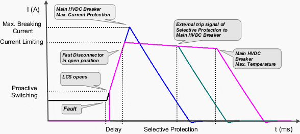
Proactive control of the hybrid HVDC breaker allows it to compensate for the time delay of the fast disconnector, if the opening time of the disconnector is less than the time required for selective protection.
 |
| Figure 2 - Proactive control of hybrid HVDC breaker. LCS denotes load commutation switch |
As shown in Figure 2, proactive current commutation is initiated by the hybrid HVDC breaker’s built-in overcurrent protection as soon as the HVDC line current exceeds a certain overcurrent level. The main HVDC breaker delays current breaking until a trip signal of the selected protection is received or the faulty line current is close to the maximum breaking current capability of the main HVDC breaker.
To extend the time before the self-protection function of the main HVDC breaker trips the hybrid HVDC breaker, the main HVDC breaker may operate in current limitation mode prior to current breaking.
The main HVDC breaker controls the voltage drop across the HVDC reactor to zero to prevent a further rise in the line current.
Pulse mode operation of the main HVDC breaker or sectionalizing the main HVDC breaker as shown in Figure 2 will allow adapting the voltage across the main HVDC breaker to the instantaneous HVDC voltage level of the HVDC grid.
The maximum duration of the current limiting mode depends on the energy dissipation capability of the arrester banks.
On-line supervision allowing maintenance on demand is achieved by scheduled current transfer of the line current from the bypass into the main HVDC current breaker during normal operation, without disturbing or interrupting the power transfer in the HVDC grid.
Fast backup protection similar to pure semiconductor breakers is possible for hybrid HVDC breakers applied to HVDC switchyards.
Due to the proactive mode, over-currents in the line or superior switchyard protection will activate the current transfer from the bypass into the main HVDC breaker or possible backup breakers prior to the trip signal of the backup protection.
In the case of a breaker failure, the backup breakers are activated almost instantaneously, typically within less than 0.2 ms. This will avoid major disturbances in the HVDC grid, and keep the required current-breaking capability of the backup breaker at reasonable values. If not utilized for backup protection, the hybrid HVDC breakers automatically return to normal operation mode after the fault is cleared.
Prototype Design Of The Hybrid HVDC Breaker
The hybrid HVDC breaker is designed to achieve a current breaking capability of 9.0 kA in an HVDC grid with rated voltage of 320 kV and rated HVDC transmission current of 2 kA. The maximum current breaking capability is independent of the current rating and depends on the design of the main HVDC breaker only.
The fast disconnector and main HVDC breaker are designed for switching voltages exceeding 1.5 p.u. in consideration of fast voltage transients during current breaking.
 |
| Figure 3 - Design of 80kV main HVDC breaker cell |
The main HVDC breaker consists of several HVDC breaker cells with individual arrester banks limiting the maximum voltage across each cell to a specific level during current breaking. Each HVDC breaker cell contains four HVDC breaker stacks as shown in Figure 3.
Two stacks are required to break the current in either current direction.
Each stack is composed of up to 20 series connected IGBT (insulated gate bipolar transistor) HVDC breaker positions.
Due to the large di/dt stress during current breaking, a mechanical design with low stray inductance is required.
Application of press pack IGBTs with 4.5 kV voltage rating [6] enables a compact stack design and ensures a stable short circuit failure mode in case of individual component failure. Individual RCD snubbers across each IGBT position ensure equal voltage distribution during current breaking.
Optically powered gate units enable operation of the IGBT HVDC breaker independent of current and voltage conditions in the HVDC grid. A cooling system is not required for the IGBT stacks, since the main HVDC breaker cells are not exposed to the line current during normal operation.
For the design of the auxiliary HVDC breaker, one IGBT HVDC breaker position for each current direction is sufficient to fulfill the requirements of the voltage rating.
Parallel connection of IGBT modules increases the rated current of the hybrid HVDC breaker. Series connected, redundant IGBT HVDC breaker positions improve the reliability of the auxiliary HVDC breaker.
A matrix of 3×3 IGBT positions for each current direction is chosen for the present design. Since the auxiliary HVDC breaker is continuously exposed to the line current, a cooling system is required.
Besides water cooling, air-forced cooling can be applied, due to relatively low losses in the range of several tens of kW only.
Comparison
Existing mechanical HVDC breakers are capable of interrupting HVDC currents within several tens of milliseconds, but this is too slow to fulfill the requirements of a reliable HVDC grid.
HVDC breakers based on semiconductors can easily overcome the limitations of operating speed, but generate large transfer losses, typically in the range of 30 percent of the losses of a voltage source converter station.
To overcome these obstacles, ABB has developed a hybrid HVDC breaker described above.
The hybrid design has negligible conduction losses, while preserving ultra-fast current interruption capability.

No comments:
Post a Comment