 |
| Arrangements of LV Utility Distribution Networks |
Introduction
In European countries the standard 3-phase 4-wire distribution voltage level is 230/400 V. Many countries are currently converting their LV systems to the latest IEC standard of 230/400 V nominal (IEC 60038).
Medium to large-sized towns and cities have underground cable distribution systems.
MV/LV distribution substations, mutually spaced at approximately 500-600 metres, are typically equipped with:
- A 3-or 4-way MV switchboard, often made up of incoming and outgoing load-break switches forming part of a ring main, and one or two MV circuit-breakers or combined fuse/ load-break switches for the transformer circuits
- One or two 1,000 kVA MV/LV transformers
- One or two (coupled) 6-or 8-way LV 3-phase 4-wire distribution fuse boards, or moulded-case circuit-breaker boards, control and protect outgoing 4-core distribution cables, generally referred to as “distributors”
The output from a transformer is connected to the LV bus bars via a load-break switch, or simply through isolating links. In densely-loaded areas, a standard size of distributor is laid to form a network, with (generally) one cable along each pavement and 4-way link boxes located in manholes at street corners, where two cables cross.
Recent trends are towards weather-proof cabinets above ground level, either against a wall, or where possible, flush-mounted in the wall. Links are inserted in such a way that distributors form radial circuits from the substation with open-ended branches (see Fig. C3).
Where a link box unites a distributor from one substation with that from a neighboring substation, the phase links are omitted or replaced by fuses, but the neutral link remains in place.
 |
| Fig. C3 : Showing one of several ways in which a LV distribution network may be arranged for radial branched-distributor operation, by removing (phase) links |
This arrangement provides a very flexible system in which a complete substation can be taken out of service, while the area normally supplied from it is fed from link boxes of the surrounding substations.
Moreover, short lengths of distributor (between two link boxes) can be isolated for fault-location and repair. Where the load density requires it, the substations are more closely spaced, and transformers up to 1,500 kVA are sometimes necessary.
Other forms of urban LV network, based on free-standing LV distribution pillars, placed above ground at strategic points in the network, are widely used in areas of lower load density. This scheme exploits the principle of tapered radial distributors in which the distribution cable conductor size is reduced as the number of consumers downstream diminish with distance from the substation.
In this scheme a number of large-sectioned LV radial feeders from the distribution board in the substation supply the busbars of a distribution pillar, from which smaller distributors supply consumers immediately surrounding the pillar.
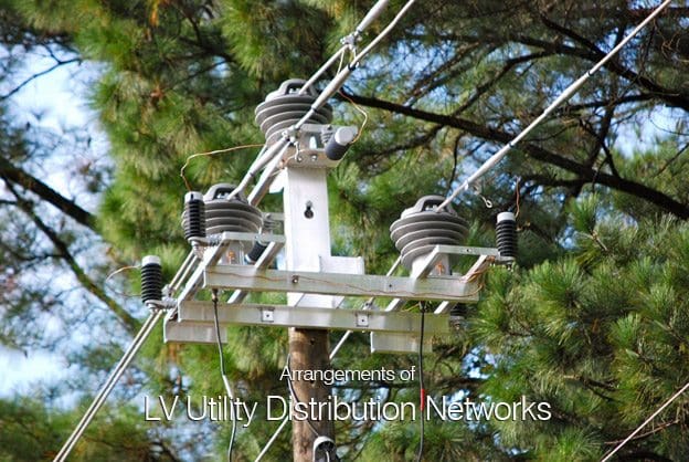
Distribution in market towns, villages and rural areas generally has, for many years, been based on bare copper conductors supported on wooden, concrete or steel poles, and supplied from pole-mounted or ground-mounted transformers.
In recent years, LV insulated conductors, twisted to form a two-core or 4-core self supporting cable for overhead use, have been developed, and are considered to be safer and visually more acceptable than bare copper lines. This is particularly so when the conductors are fixed to walls (e.g. under-eaves wiring) where they are hardly noticeable.
Improved methods using insulated twisted conductors to form a pole mounted aerial cable are now standard practice in many countriesAs a matter of interest, similar principles have been applied at higher voltages, and self supporting “bundled” insulated conductors for MV overhead installations are now available for operation at 24 kV. Where more than one substation supplies a village, arrangements are made at poles on which the LV lines from different substations meet, to interconnect corresponding phases.
North and Central American practice differs fundamentally from that in Europe, in that LV networks are practically nonexistent, and 3-phase supplies to premises in residential areas are rare.
The distribution is effectively carried out at medium voltage in a way, which again differs from standard European practices.
The MV system is, in fact, a 3-phase 4-wire system from which single-phase distribution networks (phase and neutral conductors) supply numerous single-phase transformers, the secondary windings of which are centre-tapped to produce 120/240 V single-phase 3-wire supplies.
In Europe, each utility-supply distribution substation is able to supply at LV an area corresponding to a radius of approximately 300 metres from the substation. North and Central American systems of distribution consist of a MV network from which numerous (small) MV/LV transformers each supply one or several consumers, by direct service cable (or line) from the transformer location
The central conductors provide the LV neutrals, which, together with the MV neutral conductors, are solidly earthed at intervals along their lengths. Each MV/LV transformer normally supplies one or several premises directly from the transformer position by radial service cable(s) or by overhead line(s).
Many other systems exist in these countries, but the one described appears to be the most common. Figure C4 (in next part…) shows the main features of the two systems.
Will be continued…
No comments:
Post a Comment