Friday, 21 February 2014

Revolutionary Smart-meter Software from HCC Embedded Reduces Hardware Cost and Development Time

Smart Meter File System uses structured database approach to maximize flash life and reduce power consumption 


Nürnberg, Germany 21 Feb 2014 – HCC Embedded today announced that it has developed an advanced file system, custom designed for the needs of smart-energy and smart-meter applications. HCC’s approach maximizes the life of flash, significantly reduces power consumption, and provides a deterministic ‘emergency write’ function, which reduces cost by allowing the on-board capacitor to be as small as possible. Collectively the file-system features can result in savings of many ‘cents’ for each meter, a highly significant cost reduction in high volume manufacture.
        The software is developed using high qualitydevelopment methodology and is rigorously compliant with the MISRA C:2004 coding standard.  The HCC‘Smart-meter File System™’ (SMFS™) requires less than 15kB program memory and less than 1.5kB of RAM on most 32-bit MCUs.
        Metering applications work with well-defined records that are more suited to a database approach. General-purpose file systems do not have any cyclic buffer logic for storing records and this adds complexity to applications. SMFS uses a structured database to reduce complexity of the application and improve the performance of the system in almost every way—speed, power consumption, and flash life.
Key features:
  • Fail-safe data storage for guaranteed system recovery.
  • Persistent data storage for 15 years or more.
  • Minimal power consumption to preserve battery life.
  • Minimum number of flash operations to preserve both the flash and the battery.
  • Deterministic behavior in the event of unexpected reset.
        SMFS is available immediately for a range of 16 and 32-bit MCUs and SOCs, and thanks to HCC’s Advanced Embedded Framework, can easily integrate with any RTOS, toolchain or development board. 
Visit http://www.hcc-embedded.com/ for more information.
About HCC Embedded
        HCC Embedded is a leading supplier of advanced embedded middleware for storage and communication. Implementation is based on a strong process that produces robust, target independent software modules. The company offers an extensive family of products including fail-safe file systems, IPv4 & IPv6, USB software for host and device, flash translation layers, and eTaskSync verifiable scheduler.  Thanks to the Advanced Embedded Framework, HCC software will run seamlessly in most embedded environments regardless of OS, toolchain, or hardware.  All HCC Embedded products are distributed in full source form.

Monday, 20 January 2014

T & D - 44) Types of Cable Installations in Electrical Network


Types of cable installations in electrical network

Introduction to installing power cables

There are a variety of ways to install power distribution cables. Each method ensures distribution of power with a unique degree of reliability, safety, economy, and quality for any specific set of conditions.
These conditions include the electrical characteristics of the power system, the distance and terrain of distribution, and the expected mechanical and environmental conditions.

1. Open-Wire

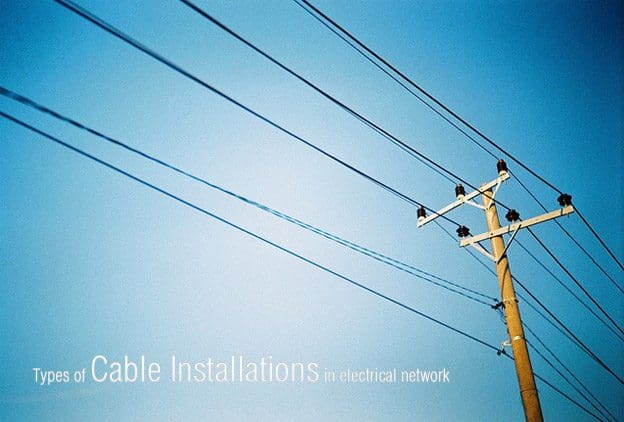
Open-wire construction consists of uninsulated conductors on insulators which are mounted on poles or structures. The conductor may be bare or it may have a thin covering for protection from corrosion or abrasion. The attractive features of this method are its low initial cost and the fact that damage can be detected and repaired quickly.
On the other hand, the uninsulated conductors are a safety hazard and are also highly susceptible to mechanical damage and electrical outages resulting from short circuits caused by birds or animals. Proper vertical clearances over roadways, walkways, and structures are critical. Exposed open-wire circuits are also more susceptible to the effects of lightning than other circuits, however, these effects may be minimized by the use of overhead ground wires and lightning arresters.
In addition, there is an increased hazard where crane or boom truck use may be involved. In some areas contamination on insulators and conductor corrosion can result in high maintenance costs.

2. Aerial Cable

Aerial cable consists of fully insulated conductors suspended above the ground. This type of installation is used increasingly, generally for replacing open wiring, where it provides greater safety and reliability and requires less space.
Properly protected cables are not a safety hazard and are not easily damaged by casual contact.
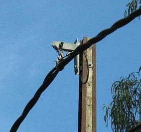
415 volt insulated aerial bundled cables (ABC)

They do, however, have the same disadvantage as open-wire construction, requiring proper vertical clearances over roadways, walkways, and structures.

2.1 Supports

Aerial cables may be either self-supporting or messenger-supported. They may be attached to pole lines or structures. Self-supporting aerial cables have high tensile strength for this application. Cables may be messenger-supported either by spirally wrapping a steel band around the cables and the messenger or by pulling the cable through rings suspended from the messenger.

2.2 Distance

Self-supporting cable is suitable for only relatively short distances, with spans in the range of 100-150 feet. Messenger-supported cable can span relatively large distances, of over 1000 feet, depending on the weight of the cable and the tensile strength of the messenger. For this reason, aerial cable that must span relatively large distances usually consists of aluminum conductors to reduce the weight of the cable assembly.
The supporting messenger provides high strength to withstand climatic rigors or mechanical shock. It may also serve as the grounding conductor of the power circuit.

3. Above-Ground Conduits

Rigid steel conduit systems afford the highest degree of mechanical protection available in above-ground conduit systems. Unfortunately, this is also a relatively high-cost system. For this reason their use is being superseded, where possible, by other types of conduit and wiring systems.
Where applicable, rigid aluminum, intermediate-grade steel conduit, thin-wall EMT, intermediate-grade metal conduit, plastic, fiber and asbestos-cement ducts are being used.

4. Underground Ducts

Underground ducts are used where it is necessary to provide a high degree of safety and mechanical protection, or where above-ground conductors would be unattractive.
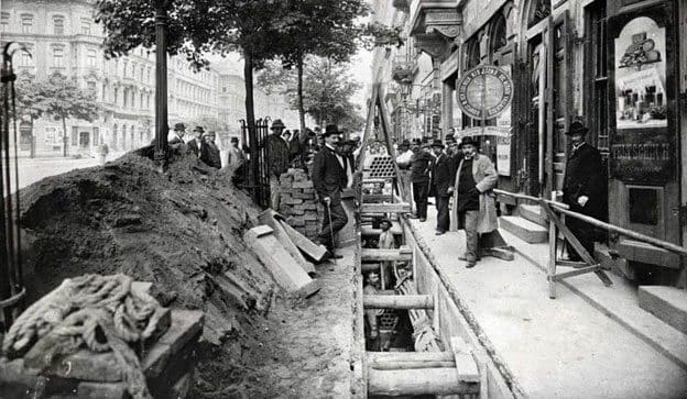
Underground cable duct on street

4.1 Construction

Underground ducts use rigid steel, plastic, fiber, and asbestos-cement conduits encased in concrete, or precast multi-hole concrete with close fitting joints.
Clay tile is also used to some extent. Where the added mechanical protection of concrete is not required, heavy wall versions of fiber and asbestos-cement and rigid steel and plastic conduits are direct buried.

4.2. Cables

Cables used in underground conduits must be suitable for use in wet areas, and protected against abrasion during installation.

5. Direct Burial
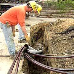
Underground  direct buried power cables
Underground direct buried power cables
Cables may be buried directly in the ground where permitted by codes and only in areas that are rarely disturbed. The cables used must be suitable for this purpose, that is, resistant to moisture, crushing,soil contaminants, and insect and rodent damage. While direct-buried cable cannot be readily added to or maintained, the current carrying capacity is usually greater than that of cables in ducts. Buried cable must have selected backfill.
It must be used only where the chance of disturbance is unlikely. The cable must be suitably protected, however, if used where the chance of disturbance is more likely to occur.
Relatively recent advances in the design and operating characteristics of cable fault location equipment and subsequent repair methods and material have diminished the maintenance problem.

6. Underwater (Submarine) Cable

Submarine cable is used only when no other cable system can be used. It supplies circuits that must cross expanses of water or swampy terrain.

6.1 Construction

Submarine cable generally consists of a lead sheathed cable and is usually armored.Insulation material should be XLP or EPR, except when paper insulation is justified because of its high resistance to, and freedom from, internal discharge or corona.
Multiconductor construction should be used, unless limited by physical factors. The lead sheathing usually consists of a copper-bearing lead material, however, other alloys may be required when special conditions warrant nonstandard sheathing. The most common type of  armoring material used for submarine cables is the spirally wrapped round galvanized steel wire.
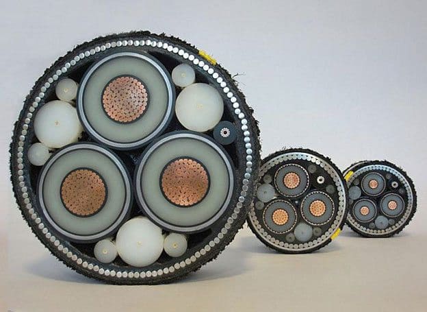
Electric power distribution undersea cable for submarine applications
Standard applications for submarine power cables to connect mainland areas or cities via water passages. This applies to mainland-to-island connections. Many of these networks and connections are getting older and need to be overhauled. We are constantly working on the continuous refinement of these products to reduce environmental effects (precisely during the laying process) and losses during power transmission (using new materials).

In this type of cable, asphalt impregnated jute is usually applied over the lead sheath and the wire armor is applied over the jute to reduce mechanical damage and electrolytic corrosion. An additional covering of the asphalt impregnated jute may be applied over the wire armor.
Nonmetallic sheathed cables are sometimes suitable for certain submarine applications. The cable must be manufactured specifically for submarine service and, generally, has an increased insulation thickness. The cable may require wire armor and should have electrical shielding for all voltage ratings above 600 V.

6.1 Installation
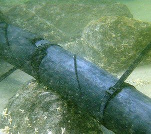
Installed underwater sea submarine cable
Submarine cable should lie on the floor of the body of water and should have ample slack so that slight shifting caused by current or turbulence will not place excessive strain on the cable. Where the cable crossing is subject to flow or tidal currents, anchors are often used to prevent excessive drifting or shifting of the cable. In addition to laying cables directly on the bottom, burying cable in a trench using the jetwater method should be considered.
Cables must be buried in waters where marine traffic is present. The depth of burial should be enough to prevent damage caused by dragging anchors, which may be in excess of 15 feet for large ships on sandy bottoms.
Warning signs located on shore at the ends of the submarine cable should be provided to prohibit anchoring in the immediate vicinity of the cable.

Grounding of Cable Systems

For safety and reliable operation, the shields and metallic sheaths of power cables must be grounded. Without such grounding, shields would operate at a potential considerably above ground. Thus, they would be hazardous to touch, and would incur rapid degradation of the jacket or other material intervening between shield and ground.
This is caused by the capacitive charging current of the cable insulation which is approximately 1 milliampere (mA) per foot of conductor length. This current normally flows at a power frequency between the conductor and the earth electrode of the cable, normally the shield. In addition, the shield or metallic sheath provides the fault return path in the event of insulation failure, permitting rapid operation of the protection devices.

Grounding Conductor

The grounding conductor, and its attachment to the shield or metallic sheath, normally at a termination or splice, should have an ampacity no lower than that of the shield.
In the case of a lead sheath, the grounding conductor must be able to carry the available fault current over its duration without overheating. Attachment to shield or sheath is frequently by means of solder, which has a low melting point; thus an adequate area of attachment is required.

Grounding Methods

The cable shield lengths may be grounded at both ends or at only one end.
If grounded at only one end, any possible fault current must traverse the length from the fault to the grounded end, imposing high current on the usually very thin shield conductor. Such a current could damage or destroy the shield, and require replacement of the entire cable rather than only the faulted section. With both ends grounded, the fault current would divide and flow to both ends, reducing the duty on the shield, with consequently less chance of damage.
There are modifications of both systems. In one, single-ended grounding may be attained by insulating the shields at each splice or sectionalizing point, and grounding only the source end of each section. This limits possible shield damage to only the faulted section.
Multiple grounding, rather than just double-ended grounding, is simply the grounding of the cable shield or sheath at all access points, such as manholes or pull boxes. This also limits possible shield damage to only the faulted section.
Resource: Electric Power Distribution Systems Operations by NAVFAC MO-201, April 1990

Sunday, 12 January 2014

T & D - 43) Reliability of Compressed Air Energy Storage Plant

Compressed air energy storage (CAES) plant

Introduction to CAES

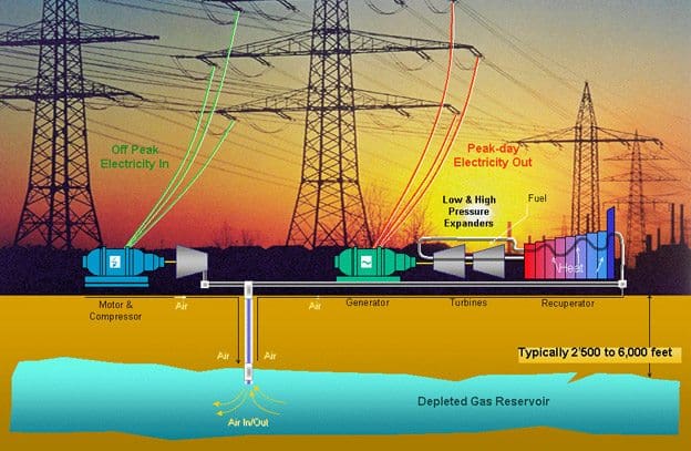
As the name implies, the compressed air energy storage (CAES) plant uses electricity to compress air which is stored in underground reservoirs. When electricity is needed, this compressed air is withdrawn, heated with gas or oil, and run through an expansion turbine to drive a generator. The compressed air can be stored in several types of underground structures, including caverns in salt or rock formations, aquifers, and depleted natural gas fields.
Typically the compressed air in a CAES plant uses about one third of the premium fuel needed to produce the same amount of electricity as in a conventional plant.
A 290-MW CAES plant has been in operation in Germany since the early 1980s with 90% availability and 99% starting reliability.
In the U.S., the Alabama Electric Cooperative runs a CAES plant that stores compressed air in a 19-million cubic foot cavern mined from a salt dome. This 110-MW plant has a storage capacity of 26 h.
290 MW Huntorf CAES station in Germany
The 290 MW Huntorf CAES station
The fixed-price turnkey cost for this first-of-a-kind plant is about $400/kW in constant 1988 dollars. The turbomachinery of the CAES plant is like a combustion turbine, but the compressor and the expander operate independently. In a combustion turbine, the air that is used to drive the turbine is compressed just prior to combustion and expansion and, as a result, the compressor and the expander must operate at the same time and must have the same air mass flow rate.
In the case of a CAES plant, the compressor and the expander can be sized independently to provide the utility-selected “optimal” MW charge and discharge rate which determines the ratio of hours of compression required for each hour of turbine-generator operation. The MW ratings and time ratio are influenced by the utility’s load curve, and the price of off-peak power.
For example, the CAES plant in Germany requires 4 h of compression per hour of generation. On the other hand, the Alabama plant requires 1.7 h of compression for each hour of generation.
At 110-MW net output, the power ratio is 0.818 kW output for each kilowatt input. The heat rate (LHV) is 4122 BTU/kWh with natural gas fuel and 4089 BTU/kWh with fuel oil.
Due to the storage option, a partial-load operation of the CAES plant is also very flexible.
For example, the heat rate of the expander increases only by 5%, and the airflow decreases nearly linearly when the plant output is turned down to 45% of full load. However, CAES plants have not reached commercial viability beyond some prototypes.
Resource: Saifur Rahman – Advanced Energy Technologies

Saturday, 11 January 2014

T & D - 42) The Structure Of Power System

The Structure Of Power System


An interconnected power system is a complex enterprise that may be subdivided into the following major subsystems:
• Generation Subsystem
• Transmission and Subtransmission Subsystem
• Distribution Subsystem
• Utilization Subsystem

Generation Subsystem

Generation subsystem includes generators and transformers.

Generators

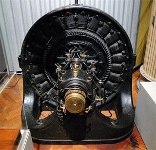
Three-phase ac generator from around 1895
An essential component of power systems is the three-phase ac generator known as synchronous generator or alternator. Synchronous generators have two synchronously rotating fields: One field is produced by the rotor driven at synchronous speed and excited by dc current. The other field is produced in the stator windings by the three-phase armature currents.
The dc current for the rotor windings is provided by excitation systems. In the older units, the exciters are dc generators mounted on the same shaft, providing excitation through slip rings. Current systems use ac generators with rotating rectifiers, known as brushless excitation systems. The excitation system maintains generator voltage and controls the reactive power flow. Because they lack the commutator, ac generators can generate high power at high voltage, typically 30 kV.
The source of the mechanical power, commonly known as the prime mover, may be hydraulic turbines, steam turbines whose energy comes from the burning of coal, gas and nuclear fuel, gas turbines, or occasionally internal combustion engines burning oil.
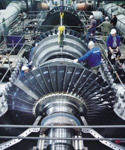
A steam turbine used to provide electric power
Steam turbines operate at relatively high speeds of3600 or 1800 rpm. The generators to which they are coupled are cylindrical rotor, two-pole for 3600 rpm, or four-pole for 1800 rpm operation. Hydraulic turbines, particularly those operating with a low pressure, operate at low speed. Their generators are usually a salient type rotor with many poles. In a power station, several generators are operated in parallel in the power grid to provide the total power needed. They are connected at a common point called a bus.
With concerns for the environment and conservation of fossil fuels, many alternate sources are considered for employing the untapped energy sources of the sun and the earth for generation of power. Some alternate sources used are solar power, geothermal power, wind power, tidal power, and biomass.
The motivation for bulk generation of power in the future is the nuclear fusion. If nuclear fusion is harnessed economically, it would provide clean energy from an abundant source of fuel, namely water.

Transformers

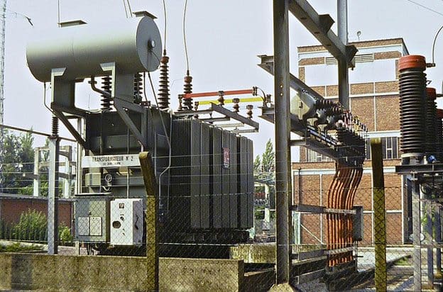
High voltage transformer 40MVA

The transformer transfers power with very high efficiency from one level of voltage to another level. The power transferred to the secondary is almost the same as the primary, except for losses in the transformer.
Using a step-up transformer will reduce losses in the line, which makes the transmission of power over long distances possible.
Insulation requirements and other practical design problems limit the generated voltage to low values, usually 30 kV. Thus, step-up transformers are used for transmission of power. At the receiving end of the transmission lines step-down transformers are used to reduce the voltage to suitable values for distribution or utilization.
The electricity in an electric power system may undergo four or five transformations between generator and consumers.

Transmission and Subtransmission Subsystem

An overhead transmission network transfers electric power from generating units to the distribution system which ultimately supplies the load.
Transmission lines also interconnect neighboring utilities which allow the economic dispatch of power within regions during normal conditions, and the transfer of power between regions during emergencies.
Standard transmission voltages are established in the United States by theAmerican National Standards Institute (ANSI). Transmission voltage lines operating at more than 60 kV are standardized at 69 kV, 115 kV, 138 kV, 161 kV, 230 kV, 345 kV, 500 kV, and 765 kV line-to-line.
Transmission voltages above 230 kV are usually referred to as extra-high voltage (EHV).
High voltage transmission lines are terminated in substations, which are called high-voltage substations, receiving substations, or primary substations.
The function of some substations is switching circuits in and out of service; they are referred to as switching stations. At the primary substations, the voltage is stepped down to a value more suitable for the next part of the trip toward the load. Very large industrial customers may be served from the transmission system.
The portion of the transmission system that connects the high-voltage substations through step-down transformers to the distribution substations is called the subtransmission network. There is no clear distinction between transmission and subtransmission voltage levels.
Typically, the subtransmission voltage level ranges from 69 to 138 kV. Some large industrial customers may be served from the subtransmission system. Capacitor banks and reactor banks are usually installed in the substations for maintaining the transmission line voltage.

Distribution Subsystem

The distribution system connects the distribution substations to the consumers’ service-entrance equipment. The primary distribution lines from 4 to 34.5 kV and supply the load in a well-defined geographical area.
Some small industrial customers are served directly by the primary feeders. The secondary distribution network reduces the voltage for utilization by commercial and residential consumers. Lines and cables not exceeding a few hundred feet in length then deliver power to the individual consumers.
The secondary distribution serves most of the customers at levels of 240/120 V, single-phase, three-wire; 208Y/120 V, three-phase, four-wire; or 480Y/277 V, three-phase, four-wire. The power for a typical home is derived from a transformer that reduces the primary feeder voltage to 240/120 V using a three-wire line.
Distribution systems are both overhead and underground. The growth of underground distribution has been extremely rapid and as much as 70 percent of new residential construction is via underground systems.

Load Subsystems

Power systems loads are divided into industrial, commercial, and residential.
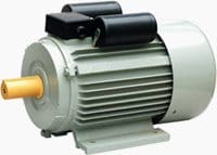
Heavy-Duty Single-Phase Capacitor Start And Run Induction Motor
Industrial loads are composite loads, and induction motorsform a high proportion of these loads. These composite loads are functions of voltage and frequency and form a major part of the system load.
Commercial and residential loads consist largely of lighting,heating, and cooking. These loads are independent of frequency and consume negligibly small reactive power. The load varies throughout the day, and power must be available to consumers on demand.
The daily-load curve of a utility is a composite of demands made by various classes of users.
The greatest value of load during a 24-hr period is called the peak or maximum demand. To assess the usefulness of the generating plant the load factoris defined. The load factor is the ratio of average load over a designated period of time to the peak load occurring in that period. Load factors may be given for a day, a month, or a year.
The yearly, or annual load factor is the most useful since a year represents a full cycle of time.
The daily load factor is:
Daily L.F. = average load / peak load            (1.1)
Multiplying the numerator and denominator of (1.1) by a time period of 24 hr, we obtain:
Daily L.F. = average load x 24 hr / peak load
Daily L.F. = energy consumed during 24 hr / peak load x 24 hr          (1.2)
The annual load factor is:
Annual L. F. =  total annual energy / peak load x 8760 hr          (1.3)
Generally there is diversity in the peak load between different classes of loads, which improves the overall system load factor.
In order for a power plant to operate economically, it must have a high system load factor. Today’s typical system load factors are in the range of 55 to 70 percent. Load-forecasting at all levels is an important function in the operation, operational planning, and planning of an electric power system. Other devices and systems are required for the satisfactory operation and protection of a power system.
Some of the protective devices directly connected to the circuits are called switchgear. They include instrument transformers, circuit breakers, disconnect switches, fuses and lightning arresters. These devices are necessary to deenergize either for normal operation or on the occurrence of faults.
The associated control equipment and protective relays are placed on switchboards in control houses.
Reference: Electrical Energy Systems by Mohamed E. El-Hawary (Dalhousie University)