Sunday, 21 July 2013

T & D - 16) FACTS – Flexible AC Transmission Systems

The acronym FACTS stands for “flexible AC transmission systems.”These systems add some of the virtues of DC, i.e., phase independence and fast controllability, to AC transmission by means of electronic controllers. Such controllers can be shunt or series connected or both. They represent variable reactances or AC voltage sources. They can provide load flow control and, by virtue of their fast controllability, damping of power swings or prevention of subsynchronous resonance (SSR).
Typical ratings of FACTS controllers range from about thirty to several hundred MVAr. Normally they are integrated in ac substations. Like HVDC converters, they require controls, cooling systems, harmonic filters, transformers, and related civil works.
Static VAR compensators (SVC) are the most common shunt-connected controllers. They are, in effect, variable reactances.
SVCs have been used successfully for many years, either for load (flicker) compen-sation of large industrial loads (arc furnaces, for example) or for transmission compensation in utility systems.
Figure 1 shows a schematic one-line diagram of an SVC, with one thyristor-controlled reactor, two thyristor switched capacitors, and one harmonic filter.
Schematic one-line diagram of an SVC
Figure 1 - Schematic one-line diagram of an SVC
1 - Transformer
2 - Thyristor- controlled reactor (TCR)
3 - Fixed connected capacitor/filter bank
4 - Thyristor-switched capacitor bank (TSC)
The thyristor controller and switches provide fast control of the overall SVC reactance between its capacitive and inductive design limits. Due to the network impedance, this capability translates into dynamic bus voltage control. As a consequence, the SVC can improve transmission stability and increase power transmission limits across a given path.
Harmonic filter and capacitor banks, reactors (normally air core), step-down transformers, breakers and disconnect switches on the high-voltage side, as well as heavy-duty buswork on the medium voltage side characterize most SVC stations. A building or an e-house with medium voltage wall bushings contains the power electronic (thyristor) controllers. The related cooler is usually located nearby.
A new type of controlled shunt compensator, a static compensator called STATCOM, uses voltage-sourced converters with high-power gate-turn-off thyristors (GTO), or IGBT [17, 18].Figure 2 shows the related one-line diagram. STATCOM is the electronic equivalent of the classical (rotating) synchro-nous condenser, and one application of STATCOM is the replacement of old synchronous condensers.
One-line diagram of a voltage sourced Static Compensator (STATCOM)
Figure 2 - One-line diagram of a voltage sourced Static Compensator (STATCOM)
The need for high control speed and low maintenance can support this choice. Where the STATCOM’s lack of inertia is a problem, it can be overcome by a sufficiently large dc capacitor. STATCOM requires fewer harmonic filters and capacitors than an SVC, and no reactors at all.
This makes the footprint of a STATCOM station significantly more compact than that of the more conventional SVC.
Like the classical fixed series capacitors (SC), thyristor-controlled series capacitors (TCSC) [19, 20] are normally located on insulated platforms, one per phase, at phase potential. Whereas the fixed SC compensates a fixed portion of the line inductance, TCSC’s effective capacitance and compensation level can be varied statically and dynamically. The variability is accomplished by a thyristor-controlled reactor connected in parallel with the main capacitor.
This circuit and the related main protection and switching components are shown in Figure 5.10. The thyristors are located in weatherproof housings on the platforms. Communication links exist between the platforms and ground. Liquid cooling is provided through ground-to-platform pipes made of insulating material.
Auxiliary platform power, where needed, is extracted from the line current via current transformers (CTs). Like most conventional SCs, TCSCs are typically integrated into existing substations. Upgrading an existing SC to TCSC is generally possible.
Schematic diagram of one phase of the Serra da Mesa (Brazil) Thyristor-controlled Series Capacitor (TCSC)
Figure 3 - Schematic diagram of one phase of the Serra da Mesa (Brazil) Thyristor-controlled Series Capacitor (TCSC)
A new development in series compensation is the thyristor-protected series compensator (TPSC). The circuit is basically the same as for TCSC, but without any controllable reactor and forced thyristor cooling.
The thyristors of a TPSC are used only as a bypass switch to protect the capacitors against overvoltage, thereby avoiding large MOV arrester banks with relatively long cool-off intervals. While SVC and STATCOM controllers are shunt devices, and TCSCs are series devices, the so-called unified power flow controller (UPFC) is a combination of both [21].
Figure 4 shows the basic circuit. The UPFC uses a shunt-connected transformer and a transformer with series-connected line windings, both interconnected to a dc capacitor via related voltage-source-converter circuitry within the control building.
One-line diagram of a Unified Power Flow Controller (UPFC)
Figure 4 - One-line diagram of a Unified Power Flow Controller (UPFC)
A more recent FACTS station project involves similar shunt and series elements as the UPFC, and this can be reconfigured to meet changing system requirements. This configuration is called a convertible static compensator (CSC).
The ease with which FACTS stations can be reconfigured or even relocated is an important factor and can influence the substation design. Changes in generation and load patterns can make such flexibility desirable.
Figure 5 shows a 500-kV AC feeder (on the left side), the transformers (three single-phase units plus one spare), the medium-voltage bus, and three thyristor-switched capacitor (TSC) banks, as well as the building that houses the thyristor switches and controls.
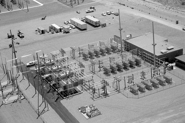
500 kV, 400 MVAr SVC at Adelanto, California
Figure 5 - 500 kV, 400 MVAr SVC at Adelanto, California (by SIEMENS)
The SVC shown in Figure 6 is connected to the 420-kV Norwegian ac grid southwest of Oslo. It uses thyristor controlled reactors (TCR) and TSCs, two each, which are visible together with the 9.3-kV high-current buswork on the right side of the building.
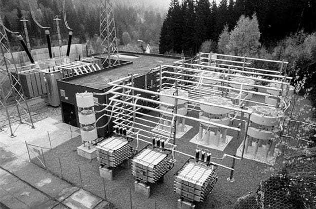
420 kV, ±160 MVAr SVC at Sylling, Norway
Figure 6 - 420 kV, ±160 MVAr SVC at Sylling, Norway (by ABB)
Figure 7 show photos of two 500-kV TCSC installations in the U.S.. The platform-mounted valve housings are clearly visible. Slatt (U.S.) has six equal TCSC modules per phase, with two valves combined in each of the three housings per bank.
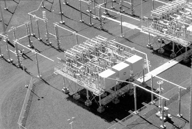
Aerial view of BPA’s Slatt, Oregon, 500kV TCSC (by GE)
Figure 7 - Aerial view of BPA’s Slatt, Oregon, 500kV TCSC (by GE)

Saturday, 20 July 2013

T & D - 15) Reducing Distribution Line Losses

Reducing Distribution Line Losses
One of the main benefits of applying capacitors is that they can reduce distribution line losses. Losses come from current through the resistance of conductors. Some of that current transmits real power, but some flows to supply reactive power. Reactive power provides magnetizing for motors and other inductive loads. Reactive power does not spin kWh meters and performs no useful work, but it must be supplied.
Using capacitors to supply reactive power reduces the amount of current in the line.
Since line losses are a function of the current squared,I2R, reducing reactive power flow on lines significantly reduces losses.
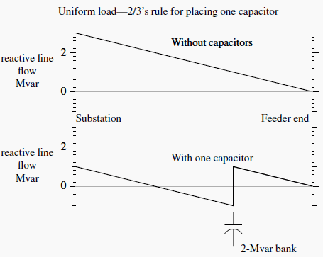
Engineers widely use the “2/3 rule” for sizing and placing capacitors to optimally reduce losses. Neagle and Samson (1956) developed a capacitor placement approach for uniformly distributed lines and showed that the optimal capacitor location is the point on the circuit where the reactive power flow equals half of the capacitor var rating. From this, they developed the 2/3 rule for selecting and placing capacitors. For a uniformly distributed load, the optimal size capacitor is 2/3 of the var requirements of the circuit.
The optimal placement of this capacitor is 2/3 of the distance from the substation to the end of the line. For this optimal placement for a uniformly distributed load, the substation source provides vars for the first 1/3 of the circuit, and the capacitor provides vars for the last 2/3 of the circuit (see Figure 1).
A generalization of the 2/3 rule for applying n capacitors to a circuit is to size each one to 2/(2n+1) of the circuit var requirements. Apply them equally spaced, starting at a distance of 2/(2n+1) of the total line length from the substation and adding the rest of the units at intervals of 2/(2n+1) of the total line length. The total vars supplied by the capacitors is 2n/(2n+1) of the circuit’s var requirements.
So to apply three capacitors, size each to 2/7 of the total vars needed, and locate them at per unit distances of 2/7, 4/7 and 6/7 of the line length from the substation.
Figure 1 - Optimal capacitor loss reduction using the two-thirds rule
Grainger and Lee (1981) provide an optimal yet simple method for placing fixed capacitors on a circuit with any load profile, not just a uniformly distributed load. With the Grainger/Lee method, we use the reactive load profile of a circuit to place capacitors.
The basic idea is again to locate banks at points on the circuit where the reactive power equals one half of the capacitor var rating.
With this 1/2-kvar rule, the capacitor supplies half of its vars downstream, and half are sent upstream. The basic steps of this approach are:1. Pick a size
Choose a standard size capacitor. Common sizes range from 300 to 1200 kvar, with some sized up to 2400 kvar. If the bank size is 2/3 of the feeder requirement, we only need one bank. If the size is 1/6 of the feeder requirement, we need five capacitor banks.
2. Locate the first bank
Start from the end of the circuit. Locate the first bank at the point on the circuit where var flows on the line are equal to half of the capacitor var rating.
3. Locate subsequent banks
After a bank is placed, reevaluate the var profile. Move upstream until the next point where the var flow equals half of the capacitor rating. Continue placing banks in this manner until no more locations meet the criteria.
There is no reason we have to stick with the same size of banks. We could place a 300-kvar bank where the var flow equals 150 kvar, then apply a 600-kvar bank where the var flow equals 300 kvar, and finally apply a 450-kvar bank where the var flow equals 225 kvar. Normally, it is more efficient to use standardized bank sizes, but different size banks at different portions of the feeder might help with voltage profiles.
The 1/2-kvar method works for any section of line. If a line has major branches, we can apply capacitors along the branches using the same method. Start at the end, move upstream, and apply capacitors at points where the line’s kvar flow equals half of the kvar rating of the capacitor. It also works for lines that already have capacitors (it does not optimize the placement of all of the banks, but it optimizes placement of new banks).
For large industrial loads, the best location is often going to be right at the load.
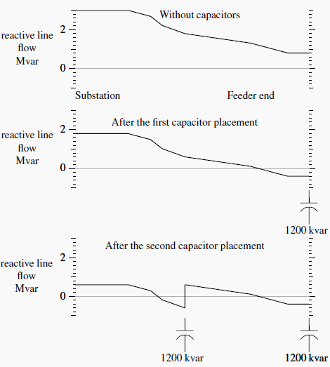
Figure 2 - Placement of 1200-kvar banks using the 1/2-kvar method
Figure 2 shows the optimal placement of 1200-kvar banks on an example circuit. Since the end of the circuit has reactive load above the 600-kvar threshold for sizing 1200-kvar banks, we apply the first capacitor at the end of the circuit. (The circuit at the end of the line could be one large customer or branches off the main line.) The second bank goes near the middle. The circuit has an express feeder near the start.
Another 1200-kvar bank could go in just after the express feeder, but that does not buy us anything. The two capacitors total 2400 kvar, and the feeder load is 3000 kvar. We really need another 600-kvar capacitor to zero out the var flow before it gets to the express feeder.
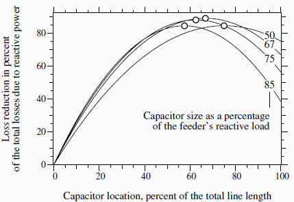
Figure 3 -Sensitivity to losses of sizing and placing one capacitor on a circuit with a uniform load
Figure 3 -Sensitivity to losses of sizing and placing one capacitor on a circuit with a uniform load. (The circles mark the optimum location for each of the sizes shown.)

Fortunately, capacitor placement and sizing does not have to be exact. Quite good loss reduction occurs even if sizing and placement are not exactly
optimum. Figure 3 shows the loss reduction for one fixed capacitor on a circuit with a uniform load. The 2/3 rule specifies that the optimum distance is 2/3 of the distance from the substation and 2/3 of the circuit’s var requirement.
As long as the size and location are somewhat close (within 10%), the not-quite-optimal capacitor placement provides almost as much loss reduction as the optimal placement.
Consider the voltage impacts of capacitors. Under light load, check that the capacitors have not raised the voltages above allowable standards. If voltage limits are exceeded, reduce the size of the capacitor banks or the number of capacitor banks until voltage limits are not exceeded. If additional loss reduction is desired, consider switched banks as discussed below.

Energy Losses

Use the average reactive loading profile to optimally size and place capacitors for energy losses. If we use the peak-load case, the 1/2-kvar method optimizes losses during the peak load. If we have a load-flow case with the average reactive load, the 1/2-kvar method or the 2/3 rule optimizes energy losses. This leads to more separation between banks and less kvars applied than if we optimize for peak losses.
If an average system case is not available, then we can estimate it by scaling the peak load case by the reactive load factor, RLF:
RLF = Average kvar Demand / Peak kvar Demand
The reactive load factor is similar to the traditional load factor except that it only considers the reactive portion of the load. If we have no information on the reactive load factor, use the total load factor. Normally, the reactive load factor is higher than the total load factor.
Example of real and reactive power profiles on a residential feeder on a peak summer day with 95% air conditioning
Figure 4 - Example of real and reactive power profiles on a residential feeder on a peak summer day with 95% air conditioning
Figure 4 shows an example of power profiles; the real power (kW) fluctuates significantly more than the reactive power (kvar).

T & D - 14) Sag and tension of transmission and distribution lines

Sag and tension of transmission and distribution lines
Sag and tension of transmission and distribution line
The energized conductors of transmission and distribution lines must be placed to totally eliminate the possibility of injury to people.
Overhead conductors, however, elongate with time, temperature, and tension, thereby changing their original positions after installation. Despite the effects of weather and loading on a line, the conductors must remain at safe distances from buildings, objects, and people or vehicles passing beneath the line at all times.
To ensure this safety, the shape of the terrain along the right-of-way, the height and lateral position of the conductor support points, and the position of the conductor between support points under all wind, ice, and temperature conditions must be known.
Bare overhead transmission or distribution conductors are typically quite flexible and uniform in weight along their length. Because of these characteristics, they take the form of a catenary (Ehrenberg, 1935; Winkelmann, 1959) between support points. The shape of the catenary changes with conductor temperature, ice and wind loading, and time. To ensure adequate vertical and horizontal clearance under all weather and electrical loadings, and to ensure that the breaking strength of the conductor is not exceeded, the behavior of the conductor catenary under all conditions must be known before the line is designed.
The future behavior of the conductor is determined through calculations commonly referred to as sag-tension calculations.
Sag-tension calculations predict the behavior of conductors based on recommended tension limits under varying loading conditions. These tension limits specify certain percentages of the conductor’s rated breaking strength that are not to be exceeded upon installation or during the life of the line.
These conditions, along with the elastic and permanent elongation properties of the conductor, provide the basis for determinating the amount of resulting sag during installation and long-term operation of the line. Accurately determined initial sag limits are essential in the line design process. Final sags and tensions depend on initial installed sags and tensions and on proper handling during installation.
The final sag shape of conductors is used to select support point heights and span lengths so that the minimum clearances will be maintained over the life of the line. If the conductor is damaged or the initial sags are incorrect, the line clearances may be violated or the conductor may break during heavy ice or wind loadings.

Friday, 5 July 2013

T & D - 13) Bus Switching Configurations In Air Insulated Substations (AIS)

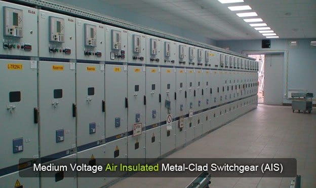
Medium Voltage Air Insulated Metal-Clad Switchgear (AIS)

Various factors affect the reliability of a substation, one of which is the arrangement of the switching devices. Arrangement of the switching devices will impact maintenance, protection, initial substation development, and cost.
There are six types of substation bus switching arrangements commonly used in air insulated substations:
1. Single bus
2. Double bus, double breaker
3. Main and transfer (inspection) bus
4. Double bus, single breaker
5. Ring bus
6. Breaker and a half

1. Single Bus Configuration

Single bus configuration

This arrangement involves one main bus with all circuits connected directly to the bus. The reliability of this type of an arrangement is very low. When properly protected by relaying, a single failure to the main bus or any circuit section between its circuit breaker and the main bus will cause an outage of the entire system. In addition, maintenance of devices on this system requires the de-energizing of the line connected to the device.
Maintenance of the bus would require the outage of the total system, use of standby generation, or switching to adjacent station, if available. Since the single bus arrangement is low in reliability, it is not recommended for heavily loaded substations or substations having a high availability requirement.
Reliability of this arrangement can be improved by the addition of a bus tiebreaker to minimize the effect of a main bus failure.

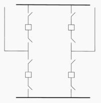
2. Double Bus, Double Breaker Configuration

Double Bus, Double Breaker Configuration
This scheme provides a very high level of reliability by having two separate breakers available to each circuit. In addition, with two separate buses, failure of a single bus will not impact either line. Maintenance of a bus or a circuit breaker in this arrangement can be accomplished without interrupting either of the circuits.
This arrangement allows various operating options as additional lines are added to the arrangement; loading on the system can be shifted by connecting lines to only one bus. A double bus, double breaker scheme is a high-cost arrangement, since each line has two breakers and requires a larger area for the substation to accommodate the additional equipment. This is especially true in a low profile configuration.
The protection scheme is also more involved than a single bus scheme.

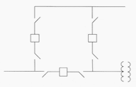
3. Main and Transfer Bus Configuration

Main and Transfer Bus Configuration
This scheme is arranged with all circuits connected between a main (operating) bus and a transfer bus (also referred to as an inspection bus). Some arrangements include a bus tie breaker that is connected between both buses with no circuits connected to it.
Since all circuits are connected to the single, main bus, reliability of this system is not very high. However, with the transfer bus available during maintenance, de-energizing of the circuit can be avoided. Some systems are operated with the transfer bus normally de-energized. When maintenance work is necessary, the transfer bus is energized by either closing the tie breaker, or when a tie breaker is not installed, closing the switches connected to the transfer bus. With these switches closed, the breaker to be maintained can be opened along with its isolation switches. Then the breaker is taken out of service. The circuit breaker remaining in service will now be connected to both circuits through the transfer bus.
This way, both circuits remain energized during maintenance. Since each circuit may have a different circuit configuration, special relay settings may be used when operating in this abnormal arrangement.
When a bus tie breaker is present, the bus tie breaker is the breaker used to replace the breaker being maintained, and the other breaker is not connected to the transfer bus. A shortcoming of this scheme is that if the main bus is taken out of service, even though the circuits can remain energized through the transfer bus and its associated switches, there would be no relay protection for the circuits. Depending on the system arrangement, this concern can be minimized through the use of circuit protection devices (reclosure or fuses) on the lines outside the substation.
This arrangement is slightly more expensive than the single bus arrangement, but does provide more flexibility during maintenance. Protection of this scheme is similar to that of the single bus arrangement. The area required for a low profile substation with a main and transfer bus scheme is also greater than that of the single bus, due to the additional switches and bus.

4. Double Bus, Single Breaker Configuration

Double Bus, Single Breaker Configuration
This scheme has two main buses connected to each line circuit breaker and a bus tie breaker. Utilizing the bus tie breaker in the closed position allows the transfer of line circuits from bus to bus by means of the switches. This arrangement allows the operation of the circuits from either bus. In this arrangement, a failure on one bus will not affect the other bus.
However, a bus tie breaker failure will cause the outage of the entire system. Operating the bus tie breaker in the normally open position defeats the advantages of the two main buses. It arranges the system into two single bus systems, which as described previously, has very low reliability. Relay protection for this scheme can be complex, depending on the system requirements, flexibility, and needs.
With two buses and a bus tie available, there is some ease in doing maintenance, but maintenance on line breakers and switches would still require outside the substation switching to avoid outages.

5. Ring Bus Configuration

Ring Bus Configuration
In this scheme, as indicated by the name, all breakers are arranged in a ring with circuits tapped between breakers. For a failure on a circuit, the two adjacent breakers will trip without affecting the rest of the system. Similarly, a single bus failure will only affect the adjacent breakers and allow the rest of the system to remain energized. However, a breaker failure or breakers that fail to trip will require adjacent breakers to be tripped to isolate the fault.
Maintenance on a circuit breaker in this scheme can be accomplished without interrupting any circuit, including the two circuits adjacent to the breaker being maintained. The breaker to be maintained is taken out of service by tripping the breaker, then opening its isolation switches. Since the other breakers adjacent to the breaker being maintained are in service, they will continue to supply the circuits. In order to gain the highest reliability with a ring bus scheme, load and source circuits should be alternated when connecting to the scheme.
Arranging the scheme in this manner will minimize the potential for the loss of the supply to the ring bus due to a breaker failure. Relaying is more complex in this scheme than some previously identified. Since there is only one bus in this scheme, the area required to develop this scheme is less than some of the previously discussed schemes. However, expansion of a ring bus is limited, due to the practical arrangement of circuits.

6. Breaker-and-a-Half Configuration

Breaker-and-a-Half Configuration
The breaker-and-a-half scheme can be developed from a ring bus arrangement as the number of circuits increases. In this scheme, each circuit is between two circuit breakers, and there are two main buses. The failure of a circuit will trip the two adjacent breakers and not interrupt any other circuit. With the three breaker arrangement for each bay, a center breaker failure will cause the loss of the two adjacent circuits. However, a breaker failure of the breaker adjacent to the bus will only interrupt one circuit.
Maintenance of a breaker on this scheme can be performed without an outage to any circuit. Further- more, either bus can be taken out of service with no interruption to the service. This is one of the most reliable arrangements, and it can continue to be expanded as required. Relaying is more involved than some schemes previously discussed.
This scheme will require more area and is costly due to the additional components.

Comparison table of configurations:

ConfigurationReliabilityCostAvailable area
.Single busLeast reliable — single failure can cause complete outageLeast cost — fewer componentsLeast area — fewer components
.Double busHighly reliable — duplicated components; single failure normally isolates single componentHigh cost — duplicated componentsGreater area — twice as many components
.Main bus and.transferLeast reliable — same as
Single bus, but flexibility in operating and maintenance with transfer bus
Moderate cost — fewer componentsLow area requirement —  fewer components
.Double bus,.single breakerModerately reliable — depends on arrangement of components and busModerate cost — more componentsModerate area — more components
.Ring busHigh reliability — single failure isolates single componentModerate cost — more componentsModerate area — increases with number of circuits
.Breaker anda.halfHighly reliable — single circuit failure isolates single circuit, bus failures do not affect circuitsModerate cost — breaker-and-a-half for each circuitGreater area — more components per circuit